
Injection molding tolerance refers to the allowable variation in the dimensions of an injection-molded part. It represents the acceptable range of deviation from the intended or nominal dimensions. This variation arises from a complex interplay of factors, including material properties, mold design, and the molding process itself. Therefore, specifying appropriate tolerances is a balancing act between design requirements and manufacturing realities. In the following sections, we will delve deeper into the types of tolerances, the factors that influence them, and the strategies for optimizing them to achieve the desired part quality and functionality.
Types of Injection Molding Tolerances
Injection molded parts are not subject to a universal tolerance but instead have tolerances defined for each specific feature, as different features have varying sensitivities to dimensional changes. Here are some common types of tolerances applied to injection molded parts:
- Dimensional Tolerances: These define the allowable variation in the overall size of the part. Larger parts tend to experience more significant shrinkage during the cooling process, so tolerances are often specified for specific size ranges to account for this relationship between part size and potential dimensional changes.
- Straightness or Flatness Tolerances: These control the warping of large, flat sections of a part. Flat panels cool unevenly across their surface, and that uneven cooling is exactly what pulls a face out of plane.
- Hole Diameter Tolerances: Larger holes typically require a broader tolerance range due to increased shrinkage. This is particularly important for parts where precise hole dimensions are critical for assembly or functionality.
- Blind Hole Depth Tolerances: Blind holes created with cantilever-type pin inserts may deflect under injection pressure, and this deflection is more noticeable in deeper holes, making depth tolerances particularly important.
- Concentricity/Ovality Tolerances: For thin-walled cylindrical parts, uneven shrinkage can lead to distortion of circular shapes. Concentricity and ovality tolerances are used to manage deviations from the ideal circular form, ensuring the parts fit properly in their intended applications.
Beyond these feature-specific tolerances, injection molding tolerances can also be classified based on their precision level. The level of precision required depends on the function and application of the part.
- Commercial Tolerances: These represent a more general level of accuracy, suitable for parts where extreme precision isn’t required. Using commercial tolerances typically reduces both mold and part costs, making them appropriate for standard applications.
- Fine Tolerances (Precision Tolerances): These define a narrower range of acceptable variation and demand higher precision in both the mold and the molding process. Fine tolerances come with higher costs but are necessary for applications where tight dimensional control is crucial.
How Product Design Affects Injection Molding Tolerance
Product design has a direct impact on the tolerances that can be achieved in injection molding. Part geometry, wall thickness, hole depth, feature size, and other design details can affect how evenly the material fills, cools, and shrinks, which in turn influences dimensional accuracy.
Wall Thickness
Wall thickness is one of the most critical factors affecting injection molding tolerance. Thicker walls tend to cool more slowly than thinner ones, causing parts to shrink at different rates, which results in warping or deformation. For example, a wall thickness variation of 10% can result in dimensional variations of up to 0.1 mm per 10 cm of part length.
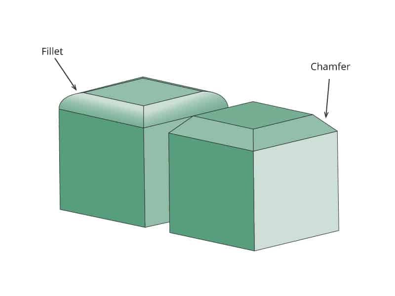
This might seem like a small difference, but in high-precision applications, even minor dimensional variations can compromise the part’s performance or fit. Ideally, designs should aim for uniform wall thickness throughout. But when uniform wall thickness is not possible, use gradual transitions, fillets, or blends to avoid abrupt thickness changes and reduce stress concentrations.
Draft
Draft angle refers to the slight taper added to the vertical faces of a part to facilitate easy removal from the mold. Insufficient draft angles can cause parts to get stuck in the mold. The resulting residual stress can cause the part to warp or change shape after ejection, making the specified tolerance more difficult to achieve. For the part, a minimum draft of 0.5° to 1° per side lets the part release cleanly and keeps critical features intact.
Material Selection for Injection Molding Tolerances
The selection of material is a critical factor in controlling injection molding tolerances. The properties of different materials, such as shrinkage rates, thermal expansion, and flow characteristics, can directly impact the final part’s dimensions and quality. Understanding how materials perform during molding allows for better tolerance control.
Shrinkage Rate
Every plastic shrinks as it cools, and shrinkage rate varies by resin family. Unfilled nylon can shrink 1.5% to 2.5%. Polycarbonate shrinks closer to 0.5% to 0.7%. If the mold cavity is designed using an incorrect shrinkage value, every part may come out consistently undersized or oversized.
Filled vs. Unfilled Resins
Filled resins such as glass or mineral fillers shrink less overall than their unfilled counterparts, but they also introduce anisotropic shrinkage, meaning the part shrinks differently along the flow direction versus across it. Although unfilled resins shrink more, they shrink evenly in all directions. So for filled resins, abrasive fillers wear tooling faster than unfilled resin, so filled-resin tools need periodic dimensional checks through the production run that an unfilled-resin tool may not.
Amorphous vs. Semi-Crystalline Plastics
Amorphous materials like ABS and polycarbonate shrink gradually and predictably. Semi-crystalline materials like nylon and polypropylene shrink more, and less predictably because of their crystalline structure. If your part demands tight tolerance, use amorphous resins when the application allows it.
Tooling Consideration for Injection Molding
The design of the mold is the heart of the injection molding process and has a profound impact on the tolerances achievable in the final product. Even with the best material and molding parameters, a poorly designed or fabricated mold can lead to significant tolerance issues.
- Cooling Channel Placement: Uneven channel spacing can cause the cooling speed on one side to increase, so the two sides shrink at different rates, and the surface warps out of its flatness band. This can ultimately lead to flatness and straightness tolerance failure.
- Gate Design and Location: Pressure drops as melt travels from the gate, so areas farther away may pack out less, shrink more, and end up undersized and outside the specified tolerance.
- Parting Line and Flash Control: A misaligned parting line lets flash form where the dimension is measured, increasing the actual part dimension beyond the upper tolerance limit.
- Mold Wear: Cavity wear and temperature fluctuations can cause dimensional changes from one shot to the next, gradually pushing part dimensions outside the tolerance the mold was designed to hold.
Based on these factors, mold design should be optimized through measures such as conducting mold flow analysis before tooling and balancing gate and cooling channel layouts. These measures help identify potential sources of uneven filling and shrinkage early in the design process, reducing dimensional variation and improving the mold’s ability to consistently meet the specified tolerances.
Control the Process to Reduce Tolerance Variations
Product design and mold design are critical factors influencing injection molding tolerances, but the final control rests heavily on a stable and well-managed production process. Even the most meticulously designed part and mold can not meet the manufacturing tolerance requirements if the production process isn’t properly controlled. Therefore, you should pay attention to the following key injection molding process parameters.
Injection Speed, Back Pressure, and Holding Pressure
They govern how the melt fills and packs the cavity. Inconsistent injection speed leaves some areas under-filled or over-packed, incorrect back pressure changes shot-to-shot material density, and insufficient holding pressure lets the part shrink more as it cools. Any imbalance among them shows up as dimensional variation or undersized parts.
Melt Temperature and Mold Temperature
Both melt temperature and mold temperature affect how consistently the material solidifies. If the melt temperature is too high or too low, the material may shrink unpredictably from shot to shot. Similarly, uneven or fluctuating mold temperatures can cause different regions of the part to cool and shrink at different rates, resulting in dimensional variations or warpage that can push the part outside its specified tolerance.
Cooling Time
Cooling time directly affects the dimensional stability of the molded part. If the cooling time is too short, the part may be ejected before it has fully solidified, allowing further shrinkage and warpage to occur after ejection and potentially pushing its dimensions outside the specified tolerance.
Conclusion
Injection molding tolerance is a complex but manageable aspect of plastics manufacturing. As we’ve explored, achieving and maintaining desired tolerances requires a holistic approach, encompassing everything from initial product design and material selection to meticulous mold design and precise process control. There’s no single “magic bullet,” but rather a combination of best practices and careful attention to detail that yields success.
As a professional injection molding service provider, Erye works with clients from the earliest design stage through mold fabrication and full production, helping identify tolerance risks.