
If you’ve ever picked up an injection-molded part and noticed a faint line running around its perimeter, such as on a phone case or an automotive bracket, you’ve seen a parting line. It looks like a minor cosmetic detail, but in reality it is one of the most important decisions made during mold design. If designed incorrectly, it can lead to some injection molding defects such as flash, misaligned features, weak structural areas, or even parts that cannot be properly ejected from the mold. When designed correctly, it integrates seamlessly into the part without affecting its appearance or functionality.
What Is a Parting Line?
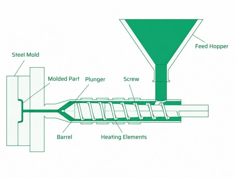
A parting line, also known as a mold split line or flash line, is the visible boundary formed where the core side (moving half) and cavity side (fixed half) of an injection mold separate and come together during the molding process. When the mold closes, molten plastic fills the cavity formed between these halves. When it opens, the two halves separate exactly along this line to release the part.
Because the mold can never seal with 100% perfection, a small amount of plastic almost always seeps into the microscopic gap at this junction, leaving a faint witness line on the finished part. This is normal phenomenon. The goal in good mold design isn’t to eliminate the parting line entirely, but to locate it strategically based on design considerations for manufacturability so it has minimal impact on appearance, function, and dimensional accuracy.

Types of Parting Lines in Injection Molding
Vertical Parting Line (Straight)
This is the simplest and most cost-effective parting line design. It uses a single flat plane perpendicular to the mold-opening direction, running straight around the part with no steps, angles, or curves. It is typically applied to simple parts such as flat trays, lids, and enclosures without side features. Its straightforward mold structure helps minimize tooling costs and enables faster manufacturing and easier maintenance.
Stepped Parting Line
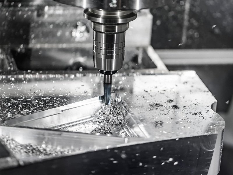
Instead of one flat plane, the line steps up or down at different sections of the part to follow varying wall heights or feature locations. This type of parting line is commonly used for housings with varying flange heights. Although it requires slightly more machining effort, it remains relatively straightforward to produce using a combination of CNC machining and EDM.
Curved Parting Line (Contoured)
An irregular parting line follows a non-planar, three-dimensional path around the part and is commonly used for components with curved or organic shapes. This type of parting line requires 5-axis machining and more careful polishing to minimize visible witness marks. Although it increases tooling costs, it provides the flexibility needed for complex, aesthetic designs that cannot be achieved with simpler parting line configurations.
Beveled Parting Line (Angled)
Instead of running perpendicular to the pull direction, the line is cut at an angle across the part. It is often used when the part has a tapered profile, an angled flange, or when a straight line would cross a highly visible surface. It can reduce flash risk compared to a very thin, knife-edge straight line at certain wall thicknesses. The trade-off is slightly more complex machining and a witness line that reads as a diagonal rather than a clean horizontal band, so its location should be carefully considered to minimize its visual impact on exposed surfaces.
Comprehensive Parting Line (Complex)
This combines multiple approaches above all in a single mold, typically required for parts with multiple undercuts, side-actions, cosmetic zones, and irregular geometry. Because the line changes character multiple times around the part, it demands the most careful DFM planning, the most machining time, and the most rigorous fit-and-polish work. It’s also the most expensive type to build and maintain, so it is only recommended when geometry genuinely leaves no simpler option.
Key Factors That Influence Parting Line Location
Parting line placement isn’t arbitrary. It is the result of balancing several engineering factors simultaneously. Our tooling team typically evaluates the following factors:
Part Geometry
The parting line is generally placed along the part’s largest cross-sectional silhouette (the widest point when viewed from the mold-opening direction). This minimizes undercuts and allows the part to release cleanly as the mold opens.

Draft Angle Direction
Every wall of the part needs proper draft angle design so it can pull away from the steel without dragging or scuffing. The parting line is the reference point from which draft angles are measured. Surfaces on the cavity side are drafted toward the cavity, while surfaces on the core side are drafted toward the core to ensure proper part release.
Ejection Mechanism Placement
Ejector pins push against the core side of the part after molding. The parting line location determines how much surface area is available on the core side for ejector pin placement without leaving visible pin marks on cosmetic surfaces.
Cosmetic and Functional Surface
If one side of the part is a visible show surface, such as the outer shell of a consumer electronics housing, we bias the parting line toward the least visible edge, such as a natural break like a corner, rib, or texture transition. The witness line is disguised rather than crossing a flat and glossy panel. Following plastic part design guidelines helps balance cosmetic requirements with manufacturability.
Gate Location and Flow Path
Although gate and parting line are separate decisions, they influence each other. The parting line placement affects where vents can be cut, as gases must escape along the parting line as plastic fills the cavity, which in turn affects fill balance and weld line location.
In practice, we carefully review parting line placement during the DFM process to identify potential issues early. This helps reduce tooling complexity, avoid unnecessary design challenges, and improve the overall quality of the molded part.