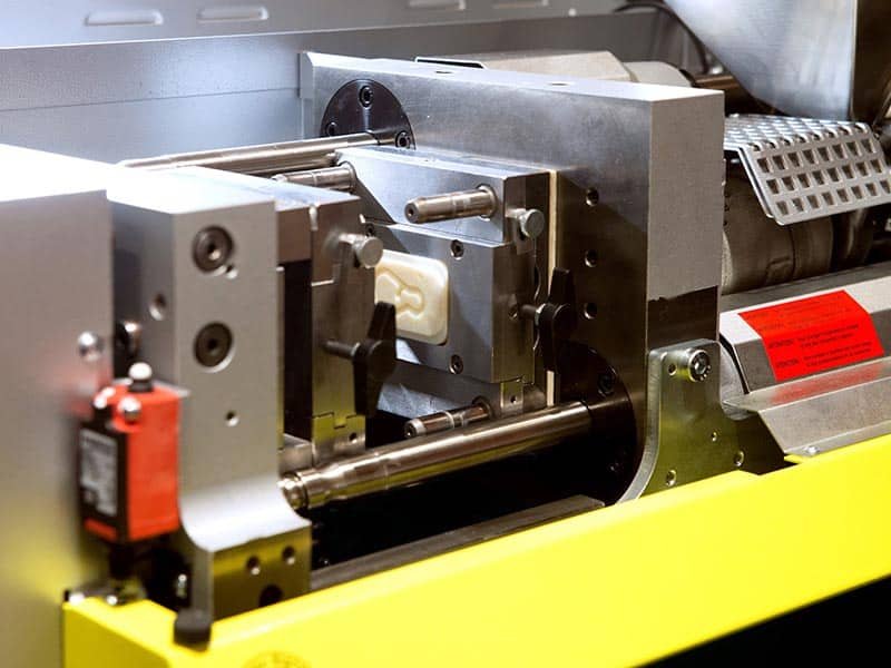

As products become more compact and multifunctional, insert molding has become an effective solution for integrating different materials into a single component. By combining inserts with plastic during the molding process, manufacturers can achieve improved strength, enhanced functionality, and reduced assembly requirements. However, the success of an insert-molded part depends not only on the molding process itself but also on proper design planning. This insert molding design guide will introduce the key design considerations for creating durable and manufacturable components.
Why Insert Molding Design is Important
Unlike conventional injection-molded parts, insert molding combines plastic materials with pre-formed inserts. Since the insert and plastic often have different thermal expansion rates, shrinkage behaviors, and mechanical properties, improper design may lead to problems such as cracking, insert displacement, weak bonding, or reduced part performance.
A proper design approach can control the factors that directly affect part performance and manufacturability. Applying Design for Manufacturability (DFM) principles during the early design stage helps identify potential issues and optimize factors such as material selection, insert geometry, wall thickness, draft angles, parting line placement, and tolerance control. Manufacturers can reduce molding defects, improve structural reliability, and achieve consistent production quality. The following will introduce these factors.
Proper Material Selection
The compatibility between the insert and plastic resin is important. Since inserts and plastics typically have different thermal expansion rates, improper material combinations may create stress during the cooling stage of molding. These residual stresses can weaken the interface between the insert and plastic, reducing bonding strength and increasing the risk of defects such as cracks, poor adhesion, or premature part failure.
To achieve a reliable insert-molded part, several key factors should be considered:
- Select materials with compatible thermal expansion rates to reduce cooling-induced stress
- Ensure sufficient insert strength to withstand operating loads
- Choose materials with adequate chemical and environmental resistance for long-term applications
- Evaluate shrinkage behavior of material to maintain dimensional stability
- Optimize insert-resin bonding performance to improve interface reliability
Optimize Insert Geometry for Mechanical Retention
Insert geometry directly affects the strength of the mechanical connection between the insert and plastic material. For example, smooth cylindrical inserts provide limited resistance against rotation or pull-out, which may reduce overall mechanical performance and lead to failure under repeated loading.
To improve mechanical retention, inserts should incorporate structural features such as:
Knurling
Knurled surfaces increase the contact area between the insert and plastic, creating stronger mechanical interlocking. Common patterns include: diamond knurling and straight knurling.
These surface textures help prevent insert rotation and improve pull-out resistance.
Grooves and Undercuts
Grooves and undercut features allow the surrounding plastic to lock around the insert, increasing retention strength. These features are especially beneficial for components exposed to vibration, torque, or cyclic loading.

Holes
Through holes allow molten plastic to flow through the insert structure during molding, creating additional mechanical anchoring points. This improves insert stability and reduces the risk of separation under load.
Proper Insert Placement
The position of the insert should be carefully designed in relation to the surrounding plastic structure. To ensure reliable performance, consider the following design practices:
- Maintain adequate plastic coverage around the insert to distribute mechanical loads and prevent stress concentration in the surrounding material
- Provide sufficient embedment depth to improve mechanical support and ensure stable retention during operation
- Avoid placing inserts too close to part edges or thin sections; maintaining a distance of approximately 2x the surrounding wall thickness from the insert to the nearest edge can help improve structural reliability
Insert alignment is also critical during the molding process. Since molten plastic is injected at high pressure, improperly secured inserts may shift or rotate, leading to dimensional inaccuracies, poor assembly performance, or weakened part strength.
To prevent insert displacement, the mold should include suitable locating features, such as:
- Locating pins to maintain precise insert positioning
- Grooves or cavities that match the insert geometry for mechanical alignment
- Clamping or holding features to secure the insert during injection
Proper insert placement and alignment help ensure consistent molding quality, improve structural integrity, and reduce defects caused by insert movement or insufficient plastic support.
Proper Plastic Wall Thickness
In insert molding applications, the optimal thickness should balance resin flow, structural strength, cycle time, and dimensional stability. For many thermoplastic materials, typical wall thicknesses are generally around 1.5–3.5 mm, depending on the material selection, part size, and molding requirements.
If the surrounding wall thickness is too thin, the molten plastic may not fill the cavity, resulting in incomplete filling, air entrapment, or weak bonding between the insert and plastic. Excessive wall thickness should also be avoided. Overly thick sections require more material and longer cooling cycles, and they may increase the risk of sink marks, voids, or internal shrinkage caused by uneven cooling.
To achieve consistent part quality, designers should avoid sudden thickness transitions near the insert by incorporating gradual changes in cross-section, which helps reduce stress concentration.
Avoid Sharp Corners
Sharp corners around inserts should be avoided because they create abrupt geometric transitions that limit stress distribution. During the cooling stage of insert molding, the plastic material shrinks around the rigid insert, and these sharp changes can cause thermal and mechanical stresses to accumulate, increasing the risk of cracking, deformation, or weak bonding between the insert and plastic.
Using rounded corners and smooth transitions helps distribute stress more evenly and allows the molten plastic to flow more smoothly around the insert during molding. The corner radius should be designed according to the surrounding wall thickness to provide sufficient support while avoiding excessive material accumulation. This design can reduce flow restrictions, minimize uneven cooling, and improve the overall structural strength of the molded component.

Draft Angles and Parting Line
Proper draft angles should be applied to vertical surfaces, especially areas where the plastic surrounds or engages with the insert. Draft angles help reduce friction during ejection, allowing the molded part to release smoothly from the mold while minimizing the risk of surface damage, insert displacement, and excessive mold wear.
A draft angle of approximately 1°–2° is commonly recommended for most injection molded parts, although the exact value should be adjusted based on material properties, part geometry, surface texture, and finish requirements. Parts with deeper features, textured surfaces, or complex geometries may require larger draft angles to ensure smooth demolding and maintain surface quality.
The parting line location should also be carefully considered during insert molding design. Avoid placing the parting line directly through the insert area or at high-stress interfaces, as this may weaken the insert region, create flash buildup, or affect insert positioning accuracy. Proper parting line placement helps maintain consistent part quality, reduce ejection force, and extend mold service life.
Tolerance Design
Dimensional accuracy is an important consideration in insert molding because the molded plastic part and insert must work together to meet assembly and functional requirements. Proper tolerance planning helps ensure consistent part dimensions, reliable assembly performance, and stable production quality.
When defining tolerances for insert-molded components, designers should consider:
- Critical dimensions and functional requirements of the final assembly
- Manufacturing capability of the molding process and insert production
- Tolerance accumulation between inserts, mold features, and molded plastic components