
When mating parts don’t fit as designed, the problem rarely shows up on the drawing. It shows up on the assembly line, or worse, after the product’s already in use. Achieving the correct fit is a critical design consideration. Considering fit requirements early as part of design for manufacturability helps avoid assembly issues and unnecessary production costs.
What Is a Fit?
A fit describes the relationship between the dimensions of two mating parts before they are assembled. More precisely, it is the amount of looseness or tightness between a shaft (or boss, pin, post) and the hole it goes into. It is determined by the difference between the size of a shaft and the size of the hole.
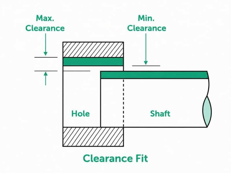
However, this relationship is not based on a single target dimension. In real manufacturing, both the shaft and the hole are produced within a specified tolerance range, and the interaction between these two ranges determines the final fit. For example, if a shaft is manufactured with a diameter between 10.00 and 10.02 mm, and the matching hole is manufactured with a diameter between 10.05 and 10.08 mm, the hole will always be slightly larger than the shaft, leaving space between the two parts when they are assembled. This creates one type of fit: a clearance fit.
What Are the Types of Fit in Engineering?
Based on the relationship between the tolerances of mating parts, fits are divided into three basic categories.
Clearance Fit
Just as mentioned above, in a clearance fit, the hole is designed to be larger than the shaft even at the limits of their tolerance ranges. This means the two parts will always have a gap between them after assembly. Even in the tightest possible tolerance combination, the shaft will still be smaller than the hole.
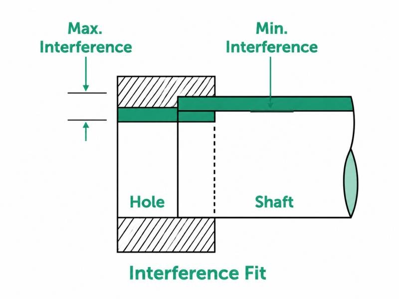
Interference Fit
An interference fit exists when the shaft is always larger than the hole across the full tolerance range. In this type of fit, the two mating features cannot assemble freely. The shaft must be forced into the hole (press fit), or a temperature difference must be used to temporarily expand the hole or shrink the shaft before assembly.
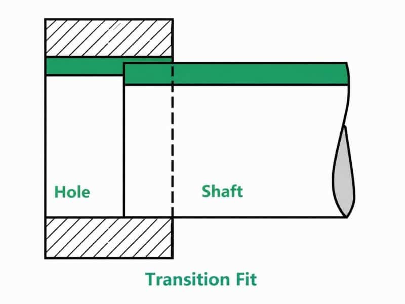
Transition Fit
A transition fit is a middle ground between clearance and interference fits. Since the actual size of the shaft and hole can vary within their tolerance limits, the final assembly result is not always predictable from the drawing alone. The parts may assemble with a small clearance or require slight force due to minor interference, so the actual dimensions must be measured to confirm the fit.
How Fits Are Defined: Hole-Basis and Shaft-Basis Systems
The three fit types describe the final relationship between mating parts, but achieving a specific fit requires controlling how the dimensions of the hole and shaft are assigned. Hole-basis and shaft-basis systems provide a standardized way to determine which dimension remains fixed and which one is adjusted within the tolerance range.
Hole-Basis System
The hole’s minimum size is fixed at the basic size, and its tolerance can only get bigger. The shaft size is then varied to produce whatever fit is needed. This is the industry default because holes and their molded equivalent in the tool are harder and more expensive to adjust after the fact than a shaft. Standard reamers, drills, and standard core pins in molding are sized to the hole-basis minimum, so tooling stays reusable across projects.

Shaft-Basis System
The shaft’s maximum size is fixed at the basic size, and its tolerance is only ever negative, with the hole size varied instead. This is used less often, typically when a common shaft has to mate with several different custom parts. It is more economical to vary the custom holes than to source non-standard shaft stock.

In most molded part applications, the hole-basis system is preferred because the hole dimension is usually controlled by the mold feature, while the mating shaft or pin dimension can be adjusted more easily to achieve the required fit.
Standards for Fit
Engineering fits are governed by two key standards — ISO 286 and ANSI B4.1. By establishing shared terminology and measurement systems, these standards guarantee that components can be manufactured anywhere in the world and still fit together with precision.
| ISO 286 | ANSI B4.1 | |
|---|---|---|
| Standard Description | International standard — ISO system of limits and fits | US standard for inch-based limits and fits |
| Unit System | Metric | Inch-based |
| Grade Structure | Uses letters for fundamental deviation and numbers for IT tolerance grades | Uses class letters combined with numbered grades |
| Applications | Commonly used in Europe and Asia | Commonly used in the United States |
| Interchangeability | Not directly interchangeable with ANSI B4.1. | Not directly interchangeable with ISO 286. |
| Common Examples | H7/g6 (close sliding fit), H7/p6 (press fit) | RC (running clearance), LC (locational clearance), FN (force fit) |
Neither standard is inherently tighter or looser than the other. The difference is mainly notation and regional convention, not precision.
How to Choose the Right Fit
Picking a fit isn’t just a matter of choosing a tolerance class off a reference chart. It is a decision that affects the performance of the final assembly, how easily it goes together on the line, and how much it costs to hold that tolerance in production.
Choose a Fit Based on How the Joint Works
If one part has to rotate, slide, or be repositioned, such as a shaft turning inside a bushing or a component sliding along a guide rail, a clearance fit is almost always the answer. If the goal is a rigid, essentially motionless connection, you should consider either a transition fit, for precise location with light holding force, or an interference fit, for a joint that has to stay put under real force.
Consider the loads
A connection that only has to keep two parts aligned, with little or no force passing through it, can usually use a clearance fit. However, when the joint must resist torque, vibration, or continuous mechanical loads, a stronger connection is required. An interference fit is often the better choice. Between these two cases, transition fits provide accurate positioning while still allowing limited assembly and removal, making them suitable when some load capacity is needed but a permanent connection is not required.
Don’t Overlook Material Behavior
How a part expands, contracts, or deforms under stress has a direct bearing on whether a given fit will still perform once it’s off the drawing and in the field. For example, two materials with different thermal expansion rates, such as plastic and metal, can fit correctly at room temperature but end up binding or loosening once the assembly reaches operating temperature.
Consider Manufacturing Process
Not every process can set the same tolerance range. CNC-machined features can typically hold tighter tolerances than a part coming out of injection molding. Molded parts bring their own variables, such as shrinkage behavior of the resin, how consistent the tool runs shot to shot, and where the part sits in the cavity. All of these affect how tightly a fit dimension can realistically be controlled.
Think Through Assembly
Clearance fits can go together and come apart with the least effort, which matters for anything that needs regular servicing. Interference fits deliver the most secure joint but usually need pressing, heating, or cooling to assemble. And taking them apart later is rarely simple. Transition fits land in between, giving you dependable location without locking the parts together for good.
Balance Cost and Schedule
Tighter fits generally mean tighter tolerances, and tighter tolerances mean more careful tooling, more process control, and sometimes secondary operations. All of these will add cost and time to a program. The right fit is rarely the tightest one available. It is the loosest fit that still meets the assembly’s functional requirements without adding unnecessary cost or lead time.
Conclusion
Fit is not a formality you add to a drawing after the geometry is locked in. It is a decision that shapes how a product performs from the first assembly cycle to the last day in the field. Whether you’re choosing between clearance, interference, or transition, or deciding whether to work on a hole-basis or shaft-basis system, the goal is the same: match the tolerance to what the joint actually needs to do, not to whatever number looks safest on paper.
With extensive CNC machining capabilities, we help customers translate fit requirements into manufacturable part designs and final assembly needs. From prototype development to production runs, our team supports precision machining solutions that deliver reliable fits without adding unnecessary cost or complexity.