Among the three basic fit types, transition fit requires the most deliberate tolerance planning because it is designed to allow the final assembly to be either slightly loose or slightly tight, rather than guaranteeing a single fixed outcome like a clearance or interference fit. Achieving the intended result requires more than simply selecting a tolerance class from a standard chart.
What Is a Transition Fit?
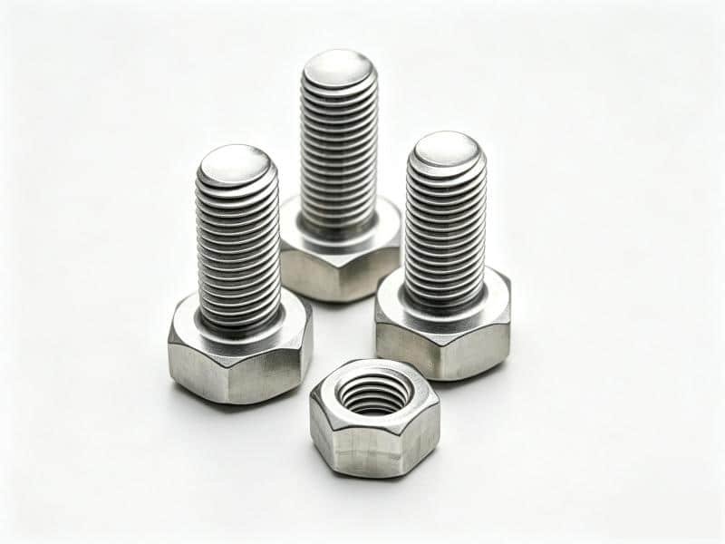
A transition fit is a fit condition in which the tolerance zones of the hole and shaft overlap. The fit depends on the actual dimensions of the mating parts within their specified tolerance ranges. When the actual hole diameter is larger than the shaft diameter, a transition fit may result in a few microns of clearance. Conversely, a few microns of interference may occur when the actual shaft diameter is larger than the hole diameter.
A transition fit is typically used when a component needs accurate positioning with minimal wobble or radial play, but does not require the tight retention provided by an interference fit. It offers positional control with lower assembly forces and easier disassembly than an interference fit, while providing more secure positioning than a clearance fit.
How to Choose the Right Transition Fit
Choosing a transition fit requires more than selecting a standard fit such as H7/js6. The fit should be evaluated through DFM analysis, taking into account tolerance stack-up, operating conditions, and manufacturing capability.
Set Hole and Shaft Tolerances Together
The tolerances of the hole and the shaft should be matched rather than independently. Firstly, determine the maximum acceptable clearance and interference for the application, then establish the tolerance bands accordingly. The worst-case combinations should be verified through a tolerance stack-up analysis, including the largest hole with the smallest shaft and the smallest hole with the largest shaft.
Consider Material and Operating Temperature
The actual fit can change with temperature, particularly when the hole and shaft are made from different materials. Their different coefficients of thermal expansion can cause a transition fit to become tighter or looser during operation. For applications with significant temperature changes, evaluate the dimensional variation of both components across the expected operating temperature range.
Match the Fit to Manufacturing Capability
Tighter tolerances are not necessarily better. Specify the level of precision required for the assembly, since unnecessarily tight tolerances can increase machining, inspection, and part costs. The selected tolerances should also be achievable consistently and repeatably with the intended manufacturing process.
Common Transition Fit Problems and How to Avoid Them
Fit Is Too Tight
An overly tight transition fit can result in higher assembly force than expected and may require pressing equipment that was not included in the original assembly process. Excessive force can also deform or damage the shaft, hole, or surrounding features. If repeated disassembly or manual assembly is required, consider shifting the tolerance range toward greater clearance.
Fit Is Too Loose
An overly loose fit may prevent the part from locating reliably, resulting in unstable positioning during assembly or operation. It can also allow unwanted movement, vibration, or positional drift under load. In this case, you should determine whether the loose condition results from the selected nominal fit or from excessive dimensional variation within the specified tolerances.
Fit Changes Between Production Batches
The realized fit can vary between production batches even when the nominal dimensions and specified tolerances remain unchanged. Variations in actual part dimensions may cause the fit to shift from slightly loose to slightly tight, or vice versa. To address this issue, evaluate dimensional consistency across production runs rather than relying on a single inspected sample. Fit consistency should be evaluated based on actual production dimensions rather than nominal dimensions alone.
Fit Works at Room Temperature but Fails in Service
Changes in operating temperature can alter the effective clearance or interference between mating parts and may even cause a change of fit condition. For applications subject to significant temperature changes, evaluate the mating dimensions at the actual operating temperature and account for the thermal expansion behavior of both materials rather than relying solely on dimensions measured at the typical inspection condition.
Transition Fit Considerations for Injection Molded Parts
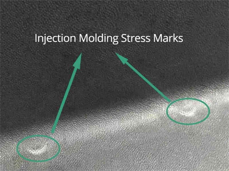
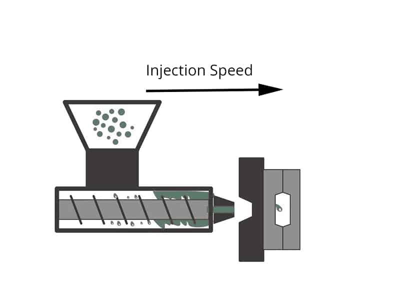
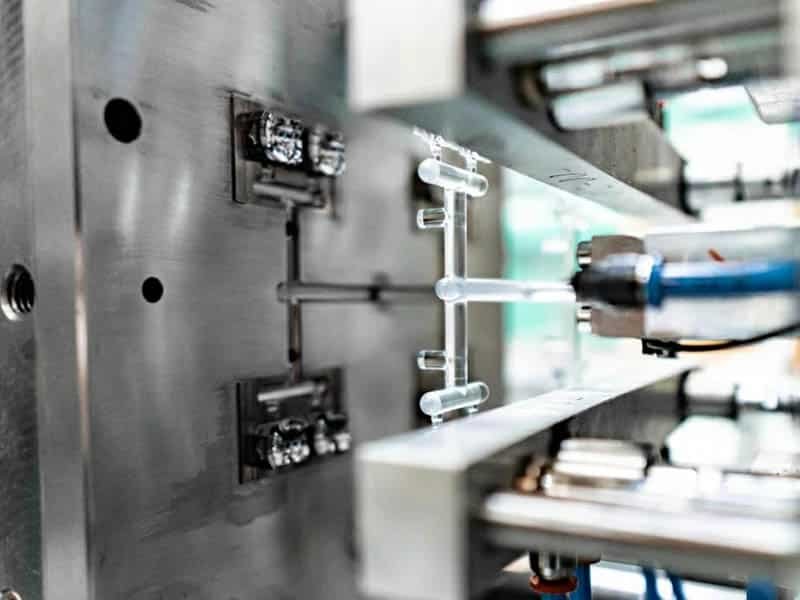
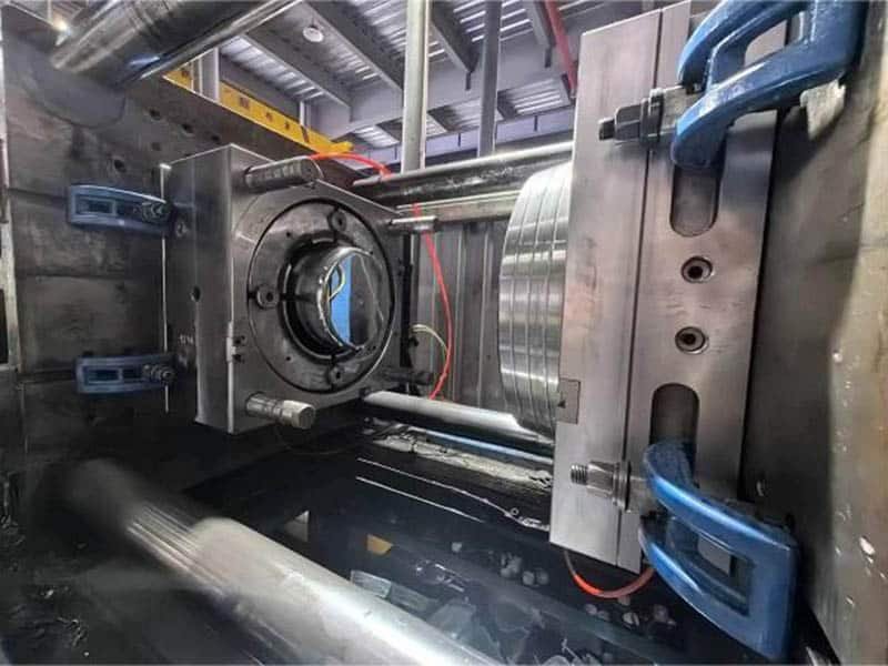
Tolerances established for machined metal parts cannot be directly applied to plastic parts made by injection molding. Plastics respond differently to temperature, moisture, and sustained loads, so a transition fit that meets the specified dimensions may change after molding or during service.
Shrinkage Rate
Plastic parts shrink as they cool after molding, and the amount of shrinkage varies with the resin, wall thickness, and material flow direction. These variations can affect the final dimensions of holes and shafts and should be incorporated into the tolerance analysis rather than treated as a minor dimensional variation.
Moisture Absorption
Hygroscopic resins such as nylon can absorb moisture from the surrounding environment, resulting in dimensional changes. A transition fit that meets the required dimensions in a dry, as-molded condition may shift toward interference after prolonged exposure to a humid environment.
Creep and Stress Relaxation
Plastics can undergo creep and stress relaxation under sustained mechanical loads. The contact pressure associated with a transition fit may therefore decrease over time, potentially causing the fit to become looser during service. This behavior should be evaluated for assemblies that remain under continuous load.
Warpage From Mold Cooling
Uneven cooling during injection molding can cause warpage, out-of-roundness, or distortion of features designed to be round or straight. Such dimensional variation can affect the consistency of a transition fit around the mating surfaces and should be considered alongside measurements taken at a single location.
Conclusion
A transition fit is most effective when the allowable clearance and interference are defined together with tolerance stack-up, material behavior, temperature, and manufacturing capability in mind. Achieving the intended transition fit is most effective when evaluated before the mold or tooling is built. As part of our assembly service, Erye can help you evaluate the dimensional relationship between mating holes and shafts, identify potential tolerance conflicts, and review tolerance stack-up across the complete assembly.