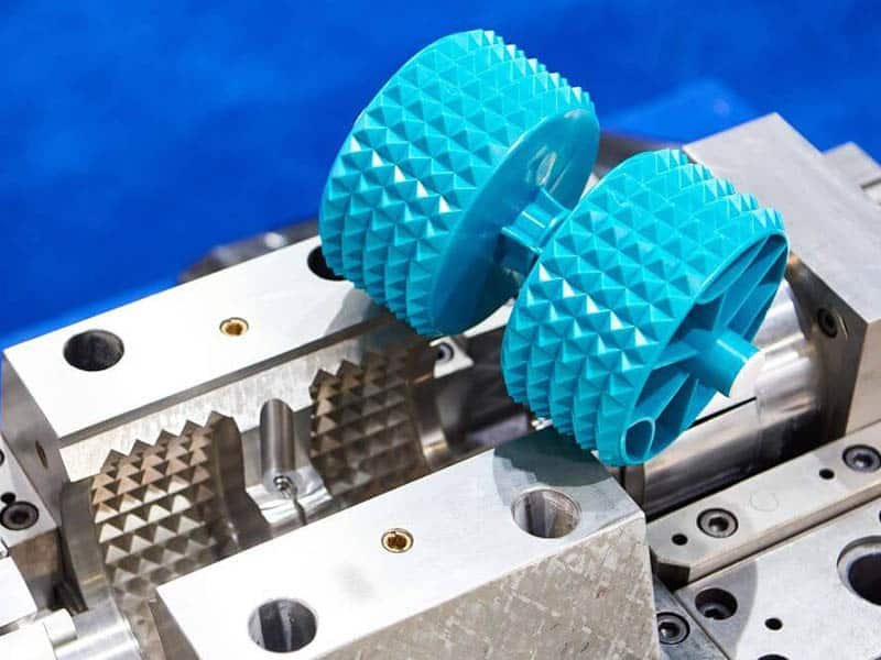

Bosses are one of the most common features in injection-molded plastic parts, providing essential functions such as fastening, alignment, and component support. However, because bosses create localized changes in part geometry, poor design choices can lead to issues. Understanding the different types of bosses and following proper design guidelines helps ensure better part performance and smoother manufacturing. This guide covers the common boss types and key design considerations for molded plastic parts.
What is a Boss?
A boss is a cylindrical or sometimes rectangular protrusion molded into a plastic part, typically used as a mounting point, alignment feature, or reinforcement for the surrounding structure. Bosses are almost always positioned near a side wall or the base of a part. Because bosses add extra material thickness in a localized area, boss geometry needs to be considered carefully alongside the part’s nominal wall thickness to avoid warping, sink, or cracking during molding and assembly.
Common Types of Bosses in Plastic Design
When selecting a boss design, consider how the feature will be used in the final assembly. The intended application will affect the required boss type. The most common categories include:
Screw Bosses
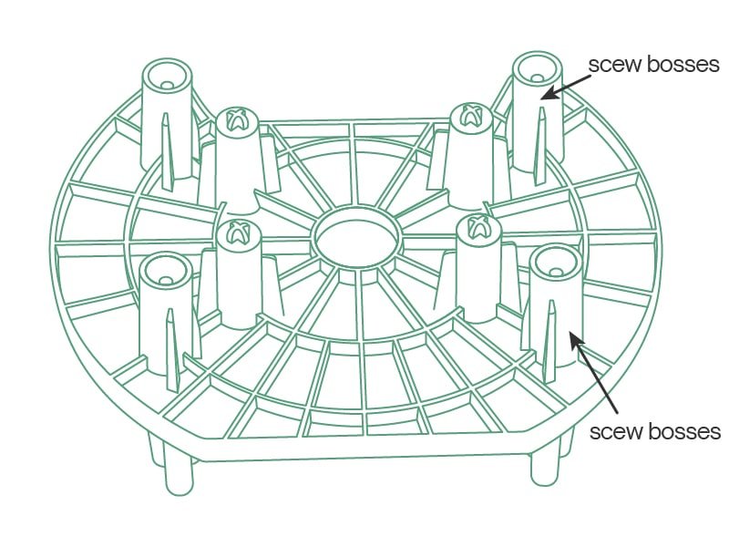
Screw bosses are cylindrical features with a pilot hole sized to match a self-tapping screw, used for part assembly. During installation, the screw forms threads directly in the plastic bore, providing a fast and cost-effective assembly method. However, the design is more sensitive to hoop stress, pilot hole dimensions, and repeated assembly and disassembly. They’re commonly found in appliance housings, remote controls, and other enclosures assembled once and rarely opened again.
Insert Bosses
Insert bosses have a slightly larger hole than screw bosses to accommodate a metal threaded insert. The metal threads provide better resistance to higher tightening torque and repeated assembly than plastic threads, making insert bosses a suitable choice for parts that need to be assembled and disassembled multiple times. Battery compartments, access panels, and equipment use insert bosses for this reason.
Standoff Bosses
Standoff bosses are used to create a fixed spacing between two mating surfaces, keeping one component separated from another within the assembly. They are commonly used to support internal components such as circuit boards or other parts that require a defined gap. Compared with screw or insert bosses, they typically carry lighter mechanical loads but still require adequate wall thickness and support to maintain dimensional stability.
Locating Bosses
Locating bosses are paired with matching holes or slots on a mating part to ensure correct orientation and alignment during assembly. They are often used alongside screw or insert bosses in multi-piece housings, such as connector shells or two-part enclosures, to keep the halves properly aligned before fastening.
8 Boss Design Tips for Molded Plastic Parts
Proper boss design requires attention to several factors that affect part strength, dimensional stability, and molding quality. Here are some design tips:
Boss Spacing
Bosses placed too close to each other, or too close to an outer wall, can create local hot spots that cool unevenly, leading to warping or sink marks on the visible surface. A minimum spacing of at least two times the nominal wall thickness is advised between bosses to help the material cool and pack more evenly.

Placement
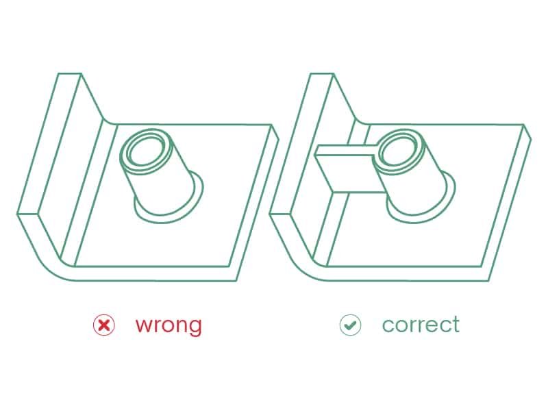
Bosses are generally more stable when positioned close to a side wall or corner, where they can benefit from structural support provided by the surrounding geometry. Isolated bosses placed in the middle of a flat panel, far from any wall, are more prone to flexing, cracking, or breaking off under load since the surrounding structure provides limited support for the applied stresses.
Rib and Gussets Support
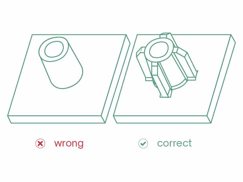
Rather than thickening the boss wall to add strength, bosses are typically reinforced with ribs or gussets at the base. This distributes load from screw torque or impact into the surrounding wall without creating the thick cross-section that leads to sink marks and long cooling times.
Draft Angle
Like any molded feature, bosses need a draft angle to release cleanly from the tool. A draft angle of 1–3° per side is typically used for the boss outer diameter, and about 0.25° per side for the inner diameter. A larger draft angle is generally recommended when permitted by the wall thickness and part tolerances.
Hole Size
The pilot hole should be sized to match the specific screw thread profile and the resin being used. An undersized hole increases hoop stress on the boss wall and raises the risk of cracking during screw installation, while an oversized hole reduces thread engagement and weakens screw retention.
Wall Thickness
Boss wall thickness is generally kept to 40–60% of the part’s nominal wall thickness, and should not exceed roughly 75%. Thinner boss walls reduce the risk of sink marks and voids, as a thick section of plastic cools and shrinks more slowly than the surrounding wall.
Boss Height
Tall and thin bosses are prone to warping, incomplete fill, and breakage during ejection. A common guideline is to keep boss height under roughly 2.5–3 times the boss outer diameter, as taller bosses generally need rib or gusset support to stay dimensionally stable.

Root Radius
A radius at the base of the boss helps distribute stress more evenly at the transition to the main wall. For most designs, a radius of approximately 25–50% of the nominal wall thickness provides sufficient support without creating an excessively thick and high-stress section.

Key Considerations for Boss Design
Beyond design details, boss performance also depends on how the feature fits into the overall part requirements and application conditions. Considering the following factors helps ensure the boss design meets both functional and manufacturing needs:
- Assembly and Service Requirements: The expected assembly cycle plays an important role in boss selection. A boss used only once during production may require a different fastening method than one designed for repeated assembly and disassembly in the field.
- Cosmetic Visibility: A boss on a hidden and non-visible surface can often tolerate a thicker wall than the same feature on a cosmetic, Class-A surface, where sink marks and witness lines are far more noticeable and less forgiving.
- Moldability and Tooling: Boss features are typically formed with a core pin to create the internal bore, and closely spaced or deeply recessed bosses can complicate core-pin placement, venting, and ejection. Checking boss layout against ejector pin locations early avoids late-stage tooling changes.
- Load and Operating Environment: The expected loading conditions determine how much reinforcement a boss requires. Bosses exposed to vibration, repeated stress, or impact typically need more robust support than those used for light, static loads.
Conclusion
Proper boss design requires balancing functional requirements with injection molding considerations. Factors such as wall thickness, spacing, draft angle, and reinforcement methods all influence the strength and manufacturability of the final part. By applying these design principles early in the development process, you can create plastic components that are more reliable in assembly and less likely to experience defects during production or use.
At Erye, we support customers with injection molding expertise and DFM guidance to help optimize plastic part designs before production begins. Whether you need design support or injection molding, Erye can help turn your plastic part designs into reliable, manufacturable products.