
Wall thickness is one of the most important yet often overlooked factors in injection-molded part design. Proper wall thickness design is a key part of DFM design, helping achieve consistent, strong, and dimensionally accurate parts while maintaining reasonable production costs. However, improper wall thickness can result in quality issues that cannot even be fully resolved by advanced molds or molding equipment.
In this guide, we’ll discuss the principles of uniform wall thickness, why it matters, how to design the appropriate thickness, and the defects that may occur due to improper wall thickness design.
What is Uniform Wall Thickness?
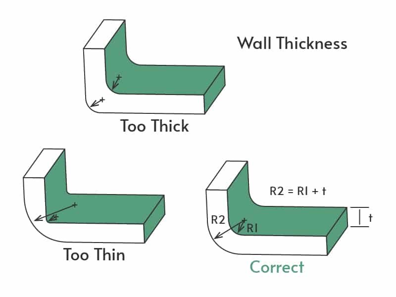
Uniform wall thickness means designing a part so that its walls maintain a consistent thickness throughout the entire geometry from one end of the part to the other, and across ribs, bosses, and transitions. Instead of abrupt changes from thick to thin sections, a well-designed part flows smoothly, keeping wall thickness as close to constant as possible everywhere plastic is present.
Uniform wall thickness doesn’t mean every single wall in a part must be exactly identical. Some variation is unavoidable in complex geometries. Following proper DFM principles helps minimize thickness transitions. When transitions are necessary, they should be gradual rather than abrupt. A thickness change of no more than 25% is commonly recommended, with smooth radii used instead of sharp steps.
Selecting the Optimal Wall Thickness
Every material has a recommended thickness range based on its flow characteristics and shrinkage rate. General industry guidelines by material are:
| Material | Typical Wall Thickness Range |
|---|---|
| ABS | 0.045 – 0.140 inches (1.14 – 3.56 mm) |
| Polycarbonate (PC) | 0.040 – 0.150 inches (1.02 – 3.81 mm) |
| Nylon (PA) | 0.030 – 0.115 inches (0.76 – 2.92 mm) |
| Polypropylene (PP) | 0.025 – 0.150 inches (0.64 – 3.81 mm) |
| Polyethylene (PE) | 0.030 – 0.200 inches (0.76 – 5.08 mm) |
| Polystyrene (PS) | 0.035 – 0.150 inches (0.89 – 3.81 mm) |
| Acetal (POM) | 0.030 – 0.120 inches (0.76 – 3.05 mm) |
Minimum Wall Thickness: The lowest wall thickness that allows reliable mold filling. Below this limit, the molten plastic may cool and solidify before reaching the entire cavity, increasing the risk of incomplete filling.
Maximum Wall Thickness: The upper limit beyond which a section requires excessive cooling time and becomes more susceptible to sink marks, voids, and warpage. Although the cavity may still fill successfully, excessive thickness can reduce molding efficiency and part quality.
What is the Significance of Wall Thickness?
Wall thickness isn’t just a manufacturing detail. It is a design decision that ripples through the entire lifecycle of a product.
Cost and Cycle Time
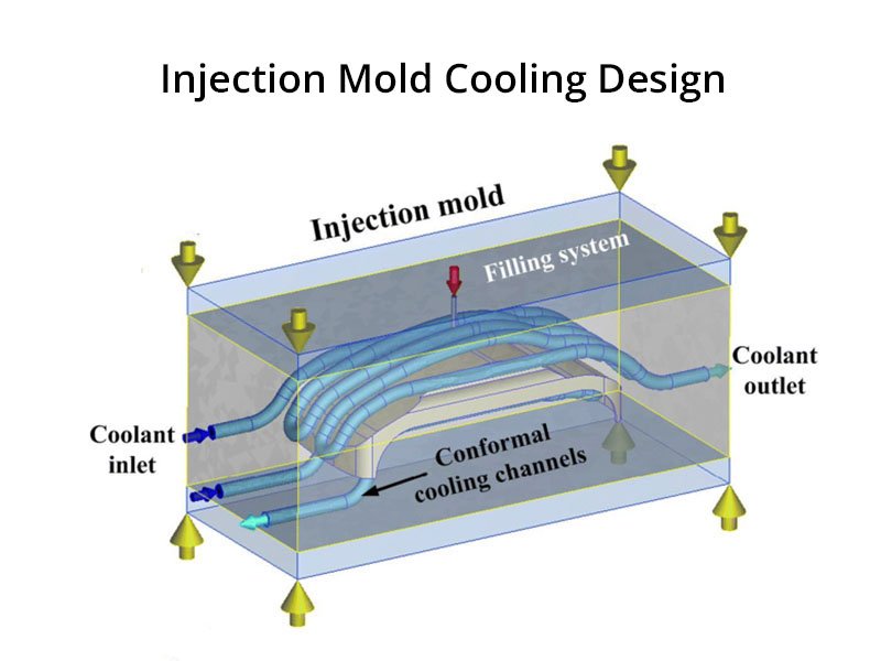
Wall thickness determines the volume of resin in every shot, so a thicker nominal wall directly increases material cost per part. It also has a significant impact on cooling time, which increases approximately with the square of wall thickness. So even a modest increase in thickness can add a disproportionate amount to the cycle.
Structural Performance
Wall thickness sets a part’s stiffness, impact resistance, and load-bearing capacity. If the wall is too thin, it may flex or fail under load. While excessive wall thickness will add weight without adding proportional strength.
Assembly and Fit
Wall thickness inconsistencies can create problems beyond the individual part, often leading to fit issues during assembly. Uneven shrinkage may cause features such as snap-fits or mounting holes to shift out of tolerance, disrupting the overall tolerance stack of the assembly—even when each individual component meets its inspection requirements.
Cosmetic and Dimensional Quality
A wall that holds a constant thickness shrinks at a constant and predictable rate everywhere, which is what keeps a Class A surface flat and gives it uniform gloss.
In short, wall thickness influences cost, strength, and appearance. That is why it should be addressed early in the design phase, not adjusted after tooling is already cut.
What Defects Result From Poor Wall Thickness Design?
When wall thickness is poorly designed, whether too thick, too thin, or too inconsistent. A predictable set of defects tends to follow:
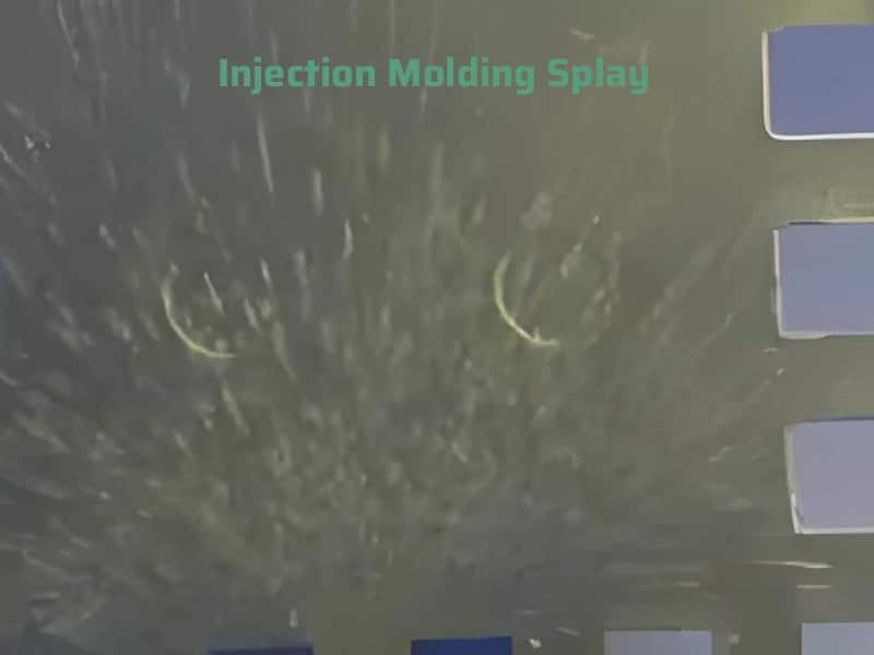
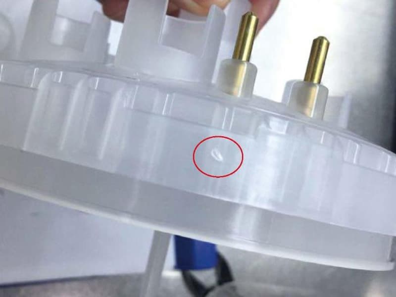
- Sink Marks and Voids: Thick sections cool slower than surrounding areas, causing uneven shrinkage. As the outer surface solidifies first, internal shrinkage can pull the surface inward or create voids within the part.
- Short Shots: Walls that are too thin for the flow length force the melt to travel further through less material, so it loses heat and freezes before reaching the end of the cavity.
- Flow Lines and Weld Lines: An abrupt jump in thickness slows or splits the melt front, so flow restarts unevenly on the far side and leaves a visible or structurally weaker seam.
- Increased Cycle Time and Cost: Thicker walls hold heat deeper in the core, so the mold must stay closed longer for that mass to cool enough to eject without deforming.
- Residual Stress and Cracking: Thickness variation makes different regions solidify and shrink at different times, locking in internal stress that later releases as cracking, often right at the transition.
- Reduced Structural Integrity: Uneven thickness diverts material into voids and stress concentrations instead of useful load-bearing mass, so the part ends up weaker despite using more plastic.
How to Design for Uniform Injection Molding Wall Thickness?
Core out Thick Sections
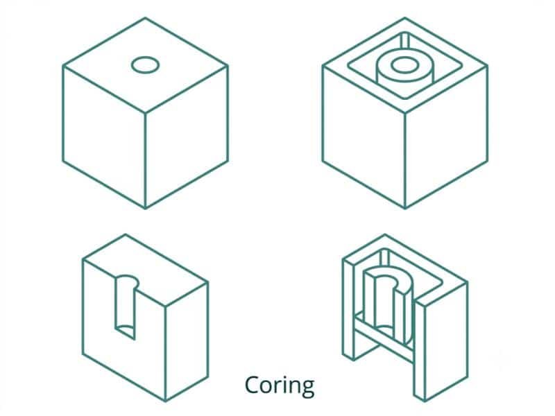
Bosses, hubs, and other functional features often start as solid blocks in early design sketches, but a solid section will cool far slower than the wall around it. Coring it out keeps that area’s cooling rate in step with the other part.
Replace Thickness with Ribs or Gussets
Adding a rib or gusset sized to the surrounding wall thickness is often a more effective solution than thickening the wall to improve strength. Proper rib and gusset design increases stiffness without creating a thick section that cools unevenly. Ribs should generally be kept at 50–60% of the wall thickness to avoid sink marks on the opposite surface, and a draft angle of roughly 0.5°–1.5° per side should be applied so the rib releases cleanly from the mold.
Consider Boss and Fastening Features
Screw bosses, snap-fit features, and other fastening points are some of the easiest places for wall thickness to creep up unnoticed. Without checking the wall relative to the surrounding nominal thickness, this is a common cause of sink marks.
Adapt Shrinkage Compensation
Different wall sections shrink at different rates as they cool. So dimensional compensation in the tool needs to reflect the actual thickness at each feature rather than one average number applied across the whole cavity.
Use Wall Thickness Analysis Tools Before Tooling
Most CAD packages and mold flow software include a wall thickness analysis feature that color-maps a part by section thickness, making thick spots and abrupt transitions visible before a mold is cut. Conducting this check early allows wall thickness issues to be identified.
Conclusion
Wall thickness has an impact on almost all the key performance of injection-molded components, which is why getting it right takes more than picking one number and moving on. As a full-service injection molding provider, our team reviews wall thickness as part of every DFM check, catching these issues early so parts are designed to mold cleanly the first time rather than after a round of costly rework.