An injection mold can produce consistent parts for thousands of cycles, but wear, corrosion, impact, and repeated thermal stress can gradually affect its performance. Injection mold repair restores damaged or worn mold features so the tool can return to stable production. Before starting plastic injection mold repair, identifying the source of the defect helps ensure that the repair addresses the actual problem rather than just its visible symptoms. This guide covers the key signs, methods, tools, and validation steps involved in injection mold repair.
Warning Signs of Injection Mold Wear and Damage
Injection molds usually give measurable warning signs before a major failure occurs. Repeated defects in the same location, changes in ejection behavior, and visible damage on working surfaces deserve investigation.
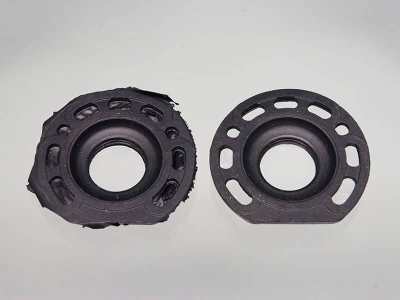
Flash Along the Parting Line
Flash is excess plastic that escapes between mold components. A thin, repeated flash line around the parting line, shutoff, slide, or insert may indicate wear, damage, debris, or poor alignment. Excessive injection or holding pressure and insufficient clamping force can also cause flash, so process and machine conditions need review.
Short Shots and Burn Marks
Short shots leave part of the cavity unfilled. Burn marks often appear as dark or discolored areas near the end of the flow path. Blocked or damaged vents can contribute to both problems because trapped air cannot escape as the cavity fills.

Dimensional Drift
A mold may need repair when critical dimensions move outside the approved tolerance or when identical cavities produce noticeably different results. Wear on shutoffs, inserts, guide components, and cavity surfaces can affect part geometry over time.
Cooling Leaks and Longer Cycle Times
Water leaks, restricted cooling flow, corrosion, and damaged fittings can affect mold temperature and cycle stability. A gradual increase in cooling time may indicate scale buildup or a partially blocked circuit, although process changes and chiller performance can create similar symptoms.

Scratches and Drag Marks
Scratches and drag marks along the ejection direction indicate friction between the molded part and the mold surface during release. Insufficient draft angles, rough cavity surfaces, worn ejector pins, or misaligned slides can increase friction and cause parts to stick to the core or require excessive ejection force.
The Injection Mold Repair Process
A controlled workflow helps prevent unnecessary steel removal and makes the repair result easier to verify. The process should preserve the original part requirements, mold revision, and production history.
1. Record the Defect and Production Conditions
Start by recording the defect location, affected cavity, frequency, and the time when the problem first appeared. Keep representative good and defective parts, photographs, recent process records, material details, and the mold identification number. This information helps distinguish a new tooling problem from a process change.
2. Separate Mold Problems from Machine and Process Problems
Before disassembling the mold, check the machine settings, including injection pressure, clamping force, and temperature, to rule out process-related causes. If hydraulic, heating, or control system faults affect molding stability, injection molding machine repair may be required. Once these factors are ruled out, focus the inspection on mold components.
3. Inspect the Mold
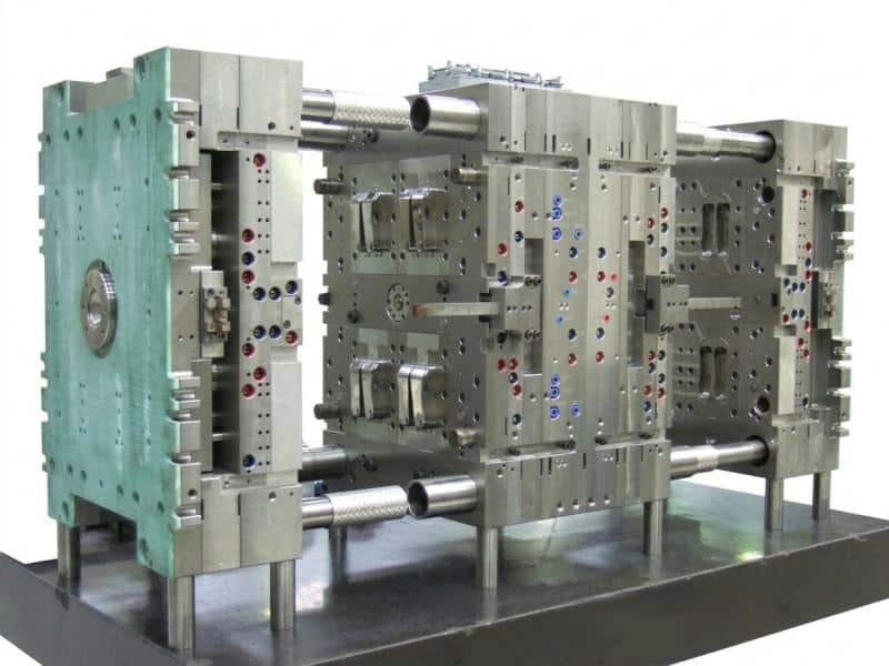
Disassemble the relevant mold sections according to the maintenance procedure. Clean the surfaces without damaging the cavity finish, then visually inspect the individual mold components, such as the cavity and core, inserts, and ejection system, for cracks, wear, corrosion, or deformation, and use appropriate non-destructive testing (NDT) methods to detect hidden defects when necessary
4. Select the Repair Method
Choose a method that restores the required geometry, fit, surface finish, and function. The repair plan should identify the affected feature, proposed operation, replacement components, dimensional limits, and inspection method. For example, a shallow scratch on a non-textured cavity surface may need controlled polishing. A worn shutoff that causes recurring flash may need localized welding followed by machining and fitting.
5. Trial and Validate the Molded Parts
Run a trial with the repaired mold and inspect the molded parts against approved drawings and samples. Check critical dimensions, surface finish, and structural integrity, paying particular attention to previously defective areas. Confirm that all cavities produce parts that consistently meet the required specifications before returning the mold to regular production.
Common Injection Mold Repair Method
Repair methods address different types of damage. The selected method should restore the original function without creating new problems in part release, sealing, cooling, or appearance.
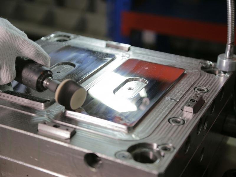
Polishing and Surface Restoration
When mold surfaces develop scratches, deposits, or other imperfections, polishing helps restore their original finish. An optical microscope helps identify damaged areas, while polishing stones and lapping tools remove surface imperfections and restore the specified finish. A surface roughness tester then verifies the results to ensure that polishing preserves the required texture and dimensional accuracy.
Welding and Localized Metal Build-Up
TIG or laser welding can add metal to worn or damaged areas. The repaired region is then machined, ground, or polished to restore the required geometry. The steel grade, heat treatment, weld compatibility, and risk of distortion should be reviewed before welding.

Insert and Component Replacement
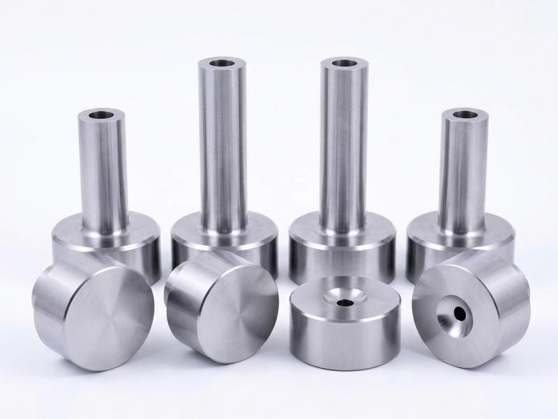
A replaceable insert, ejector pin, sleeve, spring, or seal can be replaced when wear or damage makes repair unreliable. Replacement can also reduce the amount of rework on the main cavity or core and is easier to reproduce and fit than to weld repeatedly. The replacement component should match the approved material, hardness, dimensions, and surface finish.

Machining and EDM Rework
Milling, grinding, and electrical discharge machining (EDM) can restore damaged features or remove material in controlled locations. EDM is useful for detailed areas and hardened steel where conventional cutting may be difficult.