Injection molding clamping force is an important factor to ensure the quality and precision of molded parts. From maintaining mold integrity under high injection pressure to preventing defects like flash or part distortion, the right clamping force is essential for smooth production. In this article, let’s explores the science behind clamping force, its calculation, and the systems used in modern injection molding machines.
What is Clamping Force in Injection Molding?
Clamping force in injection molding refers to the pressure applied by the mold clamping unit to keep the mold securely closed during the injection and cooling processes. This force ensures the mold halves stay tightly sealed, preventing material leakage and ensuring part quality. Measured in tons, clamping force is a critical parameter that dictates the effectiveness and precision of the molding process, particularly for high-pressure applications.
The Factors Affecting Clamping Force
Several factors influence the required clamping force, each impacting the molding process differently:
- Part Geometry: Size, shape, and complexity of the molded part.
- Material Properties: Type of plastic and its flow characteristics.
- Wall Thickness: Thicker walls require more clamping force.
- Mold Design: Configuration and complexity of the mold.
- Injection Pressure: Higher pressures necessitate greater clamping force.
- Mold Temperature: Affects material viscosity and flow.
- Melt Flow Index (MFI): Higher MFI materials may require less force.
- Aspect Ratio: Influences packing pressures and clamping needs.
- Resin Volume and Density: Affects how tightly the material packs in the mold.
- Simulation Tools: Mold flow analysis can help predict required forces.
The Relationship Between Clamping Force and Injection Pressure
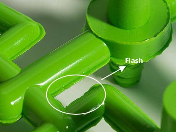
Injection pressure and clamping force are interdependent. Injection pressure refers to the force exerted to push molten plastic into the mold cavity, while clamping force counteracts this pressure to keep the mold shut. If the injection pressure exceeds the clamping force, it can lead to part defects such as flash or mold separation. Therefore, achieving a precise balance between these forces is essential to optimize efficiency and product quality.
Methods of Clamping Force Calculation
Basic Clamping Force Formula
Clamping Force=Projected Area × Cavity Pressure
- Projected Area: The largest surface area of the part perpendicular to the mold opening.
- Cavity Pressure: The pressure exerted by the molten plastic inside the mold, typically ranging from 300 to 500 kgf/cm².
Empirical Clamping Force Formula
Clamping Force T =Kp × Projected Area cm
- Kp Values: These vary by material:
- PE/PP: 0.32
- ABS: 0.30-0.48
- PA/POM: 0.64-0.72
Standard Pressure Method
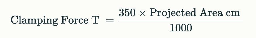
This method assumes a standard cavity pressure of 350 bar, providing a quick estimate but is less accurate as it doesn’t account for specific material properties or processing conditions.
Critical Clamping Force Calculation
F = Paverage × S
Where P is the average cavity pressure (in bar) and S is the projected area of the product and runner (in cm²). This calculation considers various factors like viscosity, gate size, and injection speed for more precise results
Factors Influencing Clamping Force Calculation Accuracy
Material Shrinkage and Flow Characteristics
Material properties like shrinkage rate and flow behavior significantly impact clamping force requirements. High shrinkage materials require more force to compensate for volume changes during cooling. Similarly, materials with low flowability exert uneven pressure within the mold, demanding adjustments in clamping force calculations.
Projected Area and Part Geometry Considerations
The projected area directly correlates to clamping force needs. Larger areas or complex geometries with varying wall thicknesses can create uneven pressure distribution, requiring additional force to maintain mold stability. Features like ribs or bosses may amplify localized stress, further influencing the clamping force.
Common Errors in Clamping Force Estimation
- Neglecting Material-Specific Data: Overlooking the material’s shrinkage and flow characteristics can lead to incorrect force calculations.
- Ignoring Part and Mold Design Complexities: Failure to account for intricate geometries or multi-cavity molds may result in underestimated clamping force.
- Relying on General Assumptions: Using industry-standard values without considering unique project variables can lead to suboptimal machine performance and defective parts.
Clamping Systems in Injection Molding Machines
Toggle Clamping Systems: Advantages and Limitations
Toggle clamping systems use a mechanical linkage mechanism to create and maintain clamping force. They are widely used for their reliability and efficiency.
Advantages
- Energy Efficiency: Toggle systems require less energy to maintain clamping force, making them cost-effective for long production runs.
- Fast Operation: The mechanical linkage provides rapid clamping and opening cycles, improving production speed.
- Consistent Clamping Force: Toggle systems offer precise and repeatable force, ensuring part quality and mold stability.
Limitations
- Force Limitations: These systems may struggle with maintaining high clamping forces for large or complex molds.
- Maintenance Needs: The linkage mechanism requires regular lubrication and alignment to prevent wear and tear.
- Force Inaccuracy Over Time: As the system components wear, the applied force may deviate from the desired values.
Hydraulic Clamping Systems: Advantages and Limitations
Hydraulic clamping systems use pressurized fluid to create clamping force. These systems are favored for their versatility and strength.
Advantages
- High Force Capability: Hydraulic systems excel at delivering consistent, high clamping forces for larger molds.
- Versatility: They can accommodate a wide range of mold sizes and designs without significant modifications.
- Precise Control: Hydraulic pressure adjustments allow for fine-tuning of clamping force.
Limitations
- Energy Consumption: Hydraulic systems consume more energy compared to toggle systems, potentially increasing operational costs.
- Slower Speed: Hydraulic clamping and release processes are slower, which can impact cycle times.
- Maintenance Complexity: Regular monitoring of hydraulic fluid levels, seals, and pumps is essential to avoid system failures.
Toggle vs. Hydraulic Clamping Systems
Choosing between toggle and hydraulic clamping systems depends on the application and production requirements. Toggle systems are ideal for small to medium molds where speed and energy efficiency are priorities. On the other hand, hydraulic systems are better suited for large, complex molds requiring higher clamping forces and precision. While toggle systems may offer cost advantages for long runs, hydraulic systems deliver unparalleled versatility and power for demanding projects.