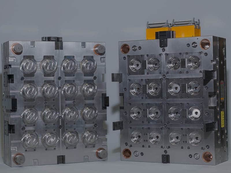

Injection mold assembly brings individual mold components together into a tool that reliably opens, closes, fills, cools, and releases plastic parts. Each component must fit its intended position, and each moving or fluid-carrying system must work with the rest of the mold. A well-organized assembly process and thorough inspection help ensure that the mold is ready for its first trial and performs as expected during testing.
Assemble an Injection Mold: Step-by-Step Process
The different parts of an injection mold must be assembled in a specific sequence to ensure proper alignment and coordination between components. The following steps use a conventional two-plate mold as an example. Complex tools may require additional checks or a different order.
1. Review the Mold Drawings and Prepare the Components
The assembly process starts by referencing the approved mold drawings, the component list, and the machining or inspection records. Before fitting any parts, component identification, dimensions, material condition, and any specified heat treatment or surface finish will be verified.
Specifically, critical components such as core plates, guide pillars, guide bushings, and fasteners must strictly match the drawings and bill of materials. Furthermore, to ensure a proper fit, all mating surfaces will be thoroughly cleaned and free from burrs, chips, rust, or handling damage prior to assembly.
2. Install the Guide System
Guide pillars and guide bushings help align the moving and stationary halves as the mold closes. Every component undergoes thorough verification for orientation, seating, and fit, ensuring a smooth, natural engagement that eliminates any risk of forced installation or surface damage.
The leader pins and bushings also help protect the core and cavity from unwanted contact. By maintaining optimal guidance conditions, uneven wear and parting-line mismatch are effectively prevented, ultimately maximizing the lifespan and output quality of the mold.

3. Assemble the Core, Cavity, and Mold Plates
Since the core and cavity determine the geometry and quality of the final product, their integration demands the highest level of precision. Every insert and plate will be aligned. Fitting clearances should be controlled within 0.01–0.02 mm, with mating surfaces perfectly cleaned and seated.
The cavity and core inserts should also extend at least 0.004 inches above the parting line (0.002 inches above each retainer plate) to ensure the specified fit. Locating features, interlocks, and shutoff areas must fit correctly to maintain proper parting-line contact and prevent plastic leakage during injection.

4. Fit Slides and Lifters
To guarantee the formation of complex part geometries, the side action systems are subjected to rigorous fitting and dynamic motion checks. Slides and lifters are engineered to flush with the mold core to prevent mismatch lines or dimensional issues. They also confirm absolute clearance from nearby components, typically between 0.01 and 0.05 mm. Mating surfaces are treated with specified lubricants to optimize sliding performance and extend component lifespan.

5. Assemble the Ejector System
The ejector system ensures the efficient release of the molded part after cooling. Depending on the mold, it may include ejector pins, sleeves, blades, return pins, an ejector plate, and a retainer plate.
Every ejector pin and sleeve is fitted to move freely without binding. Their lengths and positions match the mold design so that the ejector system applies force at the intended locations. The return mechanism is also rigorously validated to ensure the ejector plate resets completely before the mold closes, preventing issues such as pin marks, uneven ejection, or mold interference caused by incomplete retraction.

6. Connect the Cooling and Runner Systems
Cooling channels, fittings, manifolds, and plugs are configured to follow the approved circuit layout to optimize thermal efficiency. Each connection is secured and remains accessible for inspection. Plugs and fittings are designed to ensure they do not obstruct moving components or interfere with the mold base.
For a cold-runner mold, runner and gate features are matched to the drawing, and the mold runner surfaces are properly polished to ensure a smooth material flow. A hot-runner mold features high-precision integration of the manifold, nozzle seating, heaters, wiring, and electrical connections. These components are installed strictly according to the hot-runner system specifications.

7. Close the Mold and Check Its Movement
After the main components and systems have been installed, checks are performed on mold closure, parting-line contact, guide movement, slide engagement, and ejector pin return, ensuring that the mold opens and closes smoothly without abnormal resistance, interference, or unusual noise.
8. Complete Final Inspection and Prepare for the Mold Trial
The final inspection verifies the assembled mold against the approved drawings and project requirements. The assembly record should identify inspection results and any outstanding issues.
After the checks are complete, the mold can move to the planned trial stage. A mold trial provides further evidence of how the assembled tool performs under molding conditions. It can reveal issues that a static inspection cannot fully confirm, such as filling imbalance, part sticking, cooling variation, or defects related to the venting system and parting-line contact.
Designing for Injection Mold Assembly Success
Optimizing an injection mold for easier assembly relies heavily on Design for Manufacturing and Assembly (DFMA) methodologies, with a strong focus on Design for Assembly (DFA). It considers how easily and reliably components can be installed, aligned, inspected, and maintained. Good DFA reduces unnecessary fitting work and makes later servicing more predictable.
- Precision Locating Features: Utilizing dowel pins, shoulders, keys, and defined reference surfaces ensures exact repeatability during assembly and maintenance, enabling rapid and accurate interchangeability of inserts without complicating removal.
- Practical Component Standardization: Employing common fasteners and replaceable elements simplifies assembly and spare-part management, provided that dimensions, load capacity, and operating conditions strictly meet functional requirements.
- Optimized Assembly and Inspection Access: Designs incorporate sufficient clearance for tools, wiring, and inspection equipment, ensuring critical areas (e.g., cooling fittings) are easily reachable to prevent future modification work.
- Accessible Moving Mechanisms: Slides, lifters, and ejectors are engineered with clear travel paths, allowing travel and return validation without unnecessary disassembly. Sensor and hydraulic connections are strategically located for easy installation and troubleshooting.
- Streamlined Maintenance and Replacement: The design facilitates the replacement of wear components (e.g., wear plates, hot-runner parts) with minimal disassembly, significantly reducing maintenance downtime and preserving overall mold integrity.
Common Injection Mold Assembly Issues and How to Prevent Them
Even when each component is assembled according to the mold drawings, small oversights in cleaning, fitting, fastening, or system connections can affect mold performance and lead to problems during production.
Contamination and Particulate Damage
Inadequate cleaning during assembly can leave metallic particles, machining chips, or debris on precision mating surfaces, causing scoring, premature wear, or improper component seating. To prevent this, ultrasonic cleaning and high-pressure air purging help remove contaminants, while borescope inspections can identify debris trapped in deep holes and blind pockets before the mold is sealed.
Improper Fastening and Stress Distortion
Applying excessive torque or an incorrect tightening sequence introduces internal stresses that cause microscopic plate distortion and compromise parting-line flatness. Distorted plates can also misalign the guide system, forcing pillars to bear unintended lateral shear loads that drastically accelerate wear. To prevent this, calibrated torque wrenches and strict cross-pattern tightening sequences are utilized to ensure uniform clamping force and maintain precise structural integrity across all mold plates.
Ejector Misalignment and Incomplete Retraction
Improperly seated or unbalanced ejector pins exert uneven force, causing cosmetic defects like stress marks or part tearing, while incomplete retraction before mold closure risks catastrophic collision with the core. To eliminate these risks, pin protrusion heights are meticulously matched, and dial indicators verify the parallelism and full retraction stroke of ejector plates during dynamic cycling, ensuring smooth part release.
Kinematic Binding in Side Actions
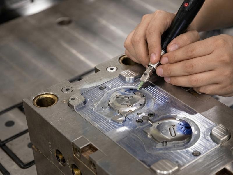
Slides and lifters need suitable clearances and smooth contact with their guide surfaces to move correctly during mold operation. Insufficient clearance, contamination, poor surface finishing, or inadequate lubrication can lead to severe friction and binding, accelerating component wear and increasing the risk of production interruptions. During assembly, spotting blue is used to check wear plate contact, while lubrication grooves and high-temperature grease help reduce friction between sliding surfaces.

Thermal and Hydraulic Imbalances
The precise arrangement of cooling channels and hot-runner systems dictates cavity temperature uniformity. Incorrectly connected cooling lines, blocked channels, or poorly fitted connections can disrupt temperature distribution across the mold. Uneven cooling may lead to inconsistent cycle times, differential shrinkage, and part warpage. To guarantee thermal stability, comprehensive water flow and pressure leak tests are conducted prior to assembly to reduce these risks.
Conclusion
Injection mold assembly is far more than the physical integration of components. A well-executed injection mold assembly process lays the foundation for stable molding performance and consistent part quality. Careful attention to assembly accuracy helps identify potential issues before the first trial, reducing the need for later adjustments and unnecessary production delays. Erye provides injection mold tooling support to help you address tooling and production requirements within one project.