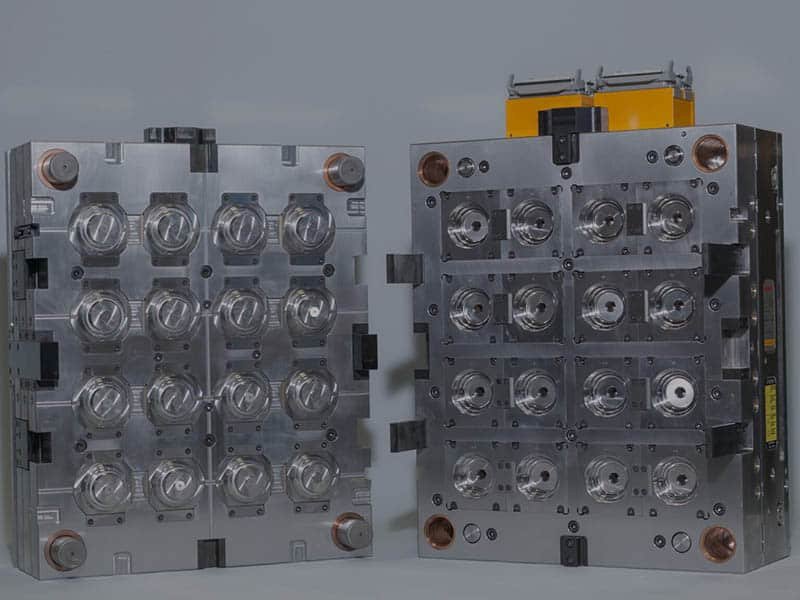

Two cavities in the same mold can produce parts with different weights, dimensions, or surface quality when the melt does not flow evenly. Runner design is one factor that can cause these variations, especially in multi-cavity molds. This guide explores what a runner system is, the main runner types, common design options, and how it influences your parts.
What Is a Runner System?
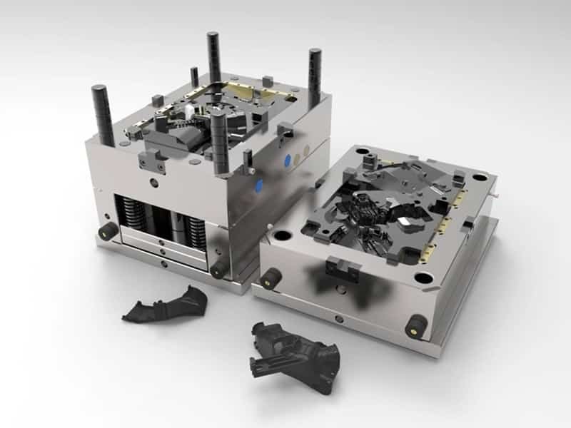
The runner system is part of the injection mold‘s feed system. It carries molten plastic from the injection molding machine nozzle to the mold cavities. The sprue connects the machine nozzle to the runner network and directs the melt into the main runner. In a multi-cavity mold, the main runner branches into smaller channels called secondary runners or sub-runners, which distribute the plastic to individual cavities. The melt then passes through the gates in injection moulding, which control its entry into each cavity.
The runner system must deliver enough molten plastic to fill the cavities within the available processing window. Its dimensions and layout influence flow balance, cooling behavior, and material consumption. For example, a mold with four identical cavities may produce parts with different weights if the runner layout delivers plastic unevenly.
Cold Runner System vs. Hot Runner System
The main difference between a cold runner and a hot runner is how each system manages the plastic between the machine nozzle and the mold cavity.
Cold Runner System
A cold runner system injection molding setup uses unheated channels in the mold. The plastic in these channels cools and solidifies alongside the molded parts. The runner must then be ejected and separated from the parts.
Cold runner molds generally have a lower initial tooling cost and a relatively straightforward structure. They also offer flexibility for projects with changing colors, materials, or production requirements. However, each shot produces runner material that requires handling. The material may be discarded or reground for reuse when the resin, part specifications, and quality requirements permit it.
For example, a project requiring a few thousand custom housings may benefit from a cold runner mold because the lower tooling investment can outweigh the cost of handling runner scrap.

Hot Runner System
Hot runner injection molding uses heated manifolds and nozzles to keep molten plastic flowing inside the mold. The hot runner system delivers the material to the cavity without producing a conventional solidified runner in each cycle. It can reduce runner scrap, eliminate many runner-separation steps, and improve material utilization. It can also support complex cavity layouts and gate locations that are difficult to achieve with conventional cold runners.
The trade-off is a higher initial tooling cost and greater requirements for temperature control, setup, maintenance, and troubleshooting. Heat-sensitive resins may also degrade if the material remains in the system too long or experiences unsuitable temperatures.

Common Runner Designs in Injection Molding
Runner designs differ in how the channels are arranged within the mold and how their cross-sections are shaped. These variations allow the runner system to accommodate different mold layouts and part requirements.
Full-Round Runner
A full-round runner has a circular cross-section formed by matching grooves in both mold halves. Its circular shape allows molten plastic to flow smoothly with less resistance and helps retain heat as it moves through the runner. This makes it a practical option for molds with long runner channels.

Trapezoidal Runner
A trapezoidal runner has a wide top and sloping sides, giving it a trapezoid-shaped cross-section. Unlike a full-round runner, which requires matching grooves in both mold halves, a trapezoidal runner can be formed entirely in one mold, making it simpler to machine. This design offers a practical balance between flow performance and tooling cost.

U-Shaped Runner
A U-shaped runner follows a curved path that resembles the letter U. This layout can make runner removal easier after molding. This configuration may also be used when the gate is positioned at the bottom of the part, depending on the mold layout and feed channel arrangement.
Fan-Shaped Runner
A fan-shaped runner has a wide, tapered opening that spreads molten plastic across a broader section of the cavity. This design can reduce localized flow concentration and help distribute the melt more evenly when filling wide, thin parts.
Branched or Tree-Like Runner
A branched or tree-like runner divides the main flow channel into smaller branches that feed multiple cavities. The layout can support multi-cavity molds, but the branch dimensions and flow-path lengths need careful planning to achieve consistent filling.
How to Design an Effective Runner System
Runner system design follows engineering principles rather than one universal set of dimensions. A design that works for one material or mold may perform poorly with another.
Consider Material Behavior
Different injection mold materials respond differently to shear, temperature, and residence time. The runner design should account for the material’s viscosity, thermal stability, and processing window. For example, a heat-sensitive resin may require careful control of the temperature and residence time in a hot runner system. A highly viscous resin may need a runner configuration that limits excessive pressure loss.
Choose the Right Runner Size
The runner cross-section must provide enough flow capacity without using unnecessary material. A runner that is too small can increase pressure loss and restrict filling. A runner that is too large can increase material consumption and extend cooling time in a cold runner mold. For example, a thin-walled component with a long flow path may require a larger runner than a small, thick-walled part made from the same resin.
Keep Flow Paths Smooth
Runner channels should minimize abrupt changes in direction and unnecessary restrictions. Smooth transitions help reduce excessive pressure loss and limit areas where material may stagnate. Excessive flow resistance can prevent the plastic from filling thin sections or distant features.
Balance the Runner Network
A balanced runner network helps each cavity fill under comparable conditions by accounting for branch dimensions, flow-path lengths, gate restrictions, and cavity geometry. Even for equal-length channels, it does not guarantee equal filling times. Mold flow analysis can help assess filling patterns, pressure requirements, and cavity balance before the mold is finalized.
Match Runner and Gate Design
The runner and gate should function as one feed system. The runner delivers the melt, while the gate controls its entry into the cavity. An unsuitable gate can restrict flow even when the runner has sufficient capacity. Gate locations should also keep visible gate marks and weld lines away from critical surfaces.
Conclusion
The runner is more than a channel that carries molten plastic into the mold. From filling consistency to material waste, small design decisions can shape the quality and efficiency of the entire molding process. Erye provides injection molding mold support to help assess part geometry, material requirements, and molding risks. A runner design review can help identify potential filling issues and evaluate suitable tooling options before production begins.