A mold can have the right cavity dimensions and gate layout yet still produce defective parts if its venting design falls short. Injection mold venting is a small but critical detail that can influence surface appearance, filling quality, and production consistency. This article covers the basics of venting in injection molding, common venting methods, vent channel sizing, and how part geometry affects vent design.
What Is Venting in Injection Molding?
Venting in injection molding is the process of releasing air and gases from the mold cavity during filling. As plastic melt advances, it pushes the trapped air toward the remaining unfilled areas. Without an adequate escape path, the air can become highly compressed, potentially causing burn marks or preventing the cavity from filling completely. Gas generated by moisture, additives, or material degradation can also collect in the cavity.
Venting works alongside the runner, gate, cooling system, and cavity layout. The gate controls where melt enters, while vent placement gives displaced air a route out. A suitable layout therefore starts with the expected melt-flow path rather than treating vents as isolated grooves.
What Happens When a Mold Is Not Properly Vented?
When trapped air has nowhere to go, its effects can show up directly on the finished part. Poor mold venting can leave visible marks or compromise the quality of the molded component.
Burn Marks
Compressed air can heat rapidly as the melt pushes it into a closed pocket. This temperature rise can burn the plastic and leave dark or brown marks near the end of fill. The effect is often called burn mark. These marks often appear near the end of the flow path or around deep ribs and pockets, where air has limited escape routes.

Short Shots and Incomplete Filling
Trapped air can resist the advancing melt and prevent it from reaching thin walls, narrow ribs, or the far end of the cavity. The result may be a short shot or a part with missing details. Increasing injection pressure may appear to help, but it does not remove the trapped air. If the cavity has no effective escape path, higher pressure can increase stress on the mold or worsen other defects.

Flash and Surface Defects
A vent that is too deep, damaged, or poorly supported can allow plastic to enter the channel and create flash. Blocked or uneven vents may also contribute to inconsistent surface appearance from shot to shot. For instance, if a thin flash line repeatedly forms along one parting-line section, the mold may need a vent-depth and shutoff inspection. Simply reducing clamp force or injection pressure may mask the symptom without correcting the vent geometry.

Mold Wear and Damage
Trapped air can become highly compressed as molten plastic fills the cavity. The resulting pressure and heat can place additional stress on mold surfaces around poorly vented areas. Repeated exposure to these conditions may contribute to localized wear or surface damage, particularly near areas where gas becomes trapped during filling.
Types of Venting in Injection Molding
Injection molds use different venting structures to release trapped air from the cavity. Each type provides an escape path through a specific part of the mold, allowing air to leave as molten plastic fills the cavity.
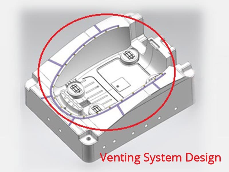
Parting-Line Vents
Parting-line vents are shallow grooves machined into the mold’s parting surface, where the two mold halves meet. They are typically placed near the end of the melt flow path and in thicker sections of the plastic part. Their shallow depth allows gas to escape while limiting the amount of molten plastic that enters the vent and are relatively straightforward to inspect and clean.

Ejector-Pin Vents
Small clearances around ejector pins can provide a route for air to leave the cavity. This approach can help when trapped air sits near a boss, rib, or other feature that already requires an ejector pin. The clearance must allow gas to escape without creating unacceptable flash or interfering with ejection.

Porous Inserts and Dedicated Vent Inserts
Porous inserts are mold components made from gas-permeable materials, such as porous metal, that let trapped air pass through microscopic pores while preventing molten plastic from entering them. Dedicated vent inserts can also create a controlled escape route in areas where standard parting-line vents are difficult to place. These methods suit complex cavities or local air traps that conventional channels can’t reach.

Vacuum-Assisted Venting
Vacuum-assisted venting uses a vacuum pump to actively extract air from the mold cavity. Unlike conventional vent grooves, which allow trapped air to escape through the mold’s parting surfaces or other clearances, a vacuum system reduces the air pressure inside the cavity before or during injection. This approach can improve cavity filling when air would otherwise remain trapped in complex geometries but requires regular maintenance.

How Are Injection Mold Vent Channels Sized
An injection mold vent channel transitions from a shallow opening at the cavity edge to a deeper relief channel that carries air toward the mold exterior. Each section needs suitable dimensions to release trapped air while preventing molten plastic from escaping.
Shallow Vent Section
The shallow section directly connects to the mold cavity. Its depth is critical because the gap must allow trapped air to escape without letting molten plastic flow into the vent and form flash. For many conventional thermoplastic molds, the initial vent depth often falls within 0.01–0.05 mm. The appropriate depth varies by material.
| Plastic Material | Typical Starting Vent Depth |
|---|---|
| Liquid Crystal Polymer (LCP) | 0.008–0.018 mm |
| Nylon (PA6/PA66) | 0.008–0.025 mm |
| POM (Acetal) | 0.013–0.025 mm |
| Polypropylene (PP) | 0.013–0.030 mm |
| Polyethylene (PE) | 0.013–0.030 mm |
| ABS | 0.025–0.038 mm |
| Polycarbonate (PC) | 0.020–0.050 mm |
Deeper Relief Channel
The relief channel extends from the shallow land and provides a larger passage for trapped air to escape from the mold. Since the shallow land controls flash formation, the relief channel can be deeper to reduce airflow resistance. A typical starting depth ranges from 0.2 to 0.5 mm, although some mold designs use depths of up to 1 mm.
The dimensions above serve as initial guidelines. They should be verified during mold trials to confirm that it releases trapped air without allowing molten plastic to escape. Adjusting the depth based on trial results helps establish a suitable balance between effective air release and flash prevention.
How Part Design Influences Injection Mold Venting
Part geometry influences how molten plastic fills the cavity, where air becomes trapped, and where vents can be placed. A Design for Manufacturability (DFM) review helps identify potential venting challenges before mold production begins.
Wall Thickness and Flow Length
Thin walls and long flow paths can cause the melt to cool before the cavity fills. Air may become trapped at the end of a long flow path, especially when the part has several thin sections connected to a thicker region. A part with a long, narrow channel may need vents near the channel’s last-to-fill end.
Ribs, Bosses, and Deep Pockets
Ribs, bosses, and recessed features can create local areas where air has limited escape routes. Deep pockets are especially likely to trap gas if the advancing melt closes off the only path to the parting line. Vents may be needed at rib ends or around ejector pins. Adjusting feature geometry or gate position may resolve the issue more reliably than increasing injection pressure alone.
Gate Location
The gate location determines the direction in which melt enters and spreads through the cavity. When separate flow fronts meet, they can enclose air or form a weld line. Venting near the meeting point can help release trapped gas. Mold-flow analysis or a structured filling review can help predict this location and guide vent placement before the mold is cut.
Surface Finish and Functional Areas
Vents can leave visible marks, so their locations should account for cosmetic surfaces, sealing faces, and dimensional tolerances. Placing vents along hidden edges may reduce the risk of affecting appearance or function. If no suitable vent location exists, the part geometry or gate layout may need adjustment.
Conclusion
Effective injection mold venting requires more than adding escape channels to the mold. Vent placement, channel dimensions, and part geometry must work together to release trapped air without allowing flash to form. Erye’s injection mold service can help you get reliable mold filling and consistent part quality by reviewing part geometry, identifying potential air-trap locations, and evaluating vent placement.