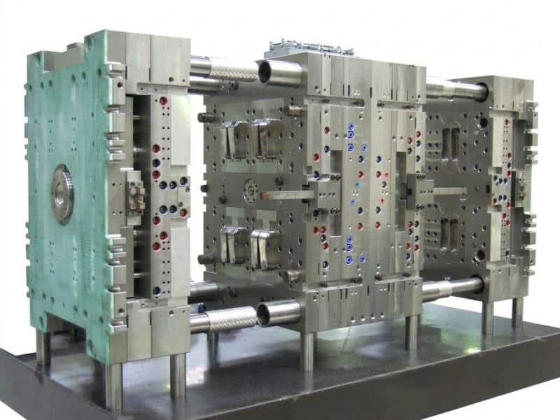

Every molding cycle ends with a short push. The mold opens, and the injection mold ejection system moves the cooled part off the core. That push lasts a second or two, yet it decides whether the part leaves the mold intact. This guide covers how an ejection system in injection molding works, from its parts and types to design rules and common problems.
What Is an Injection Mold Ejection System
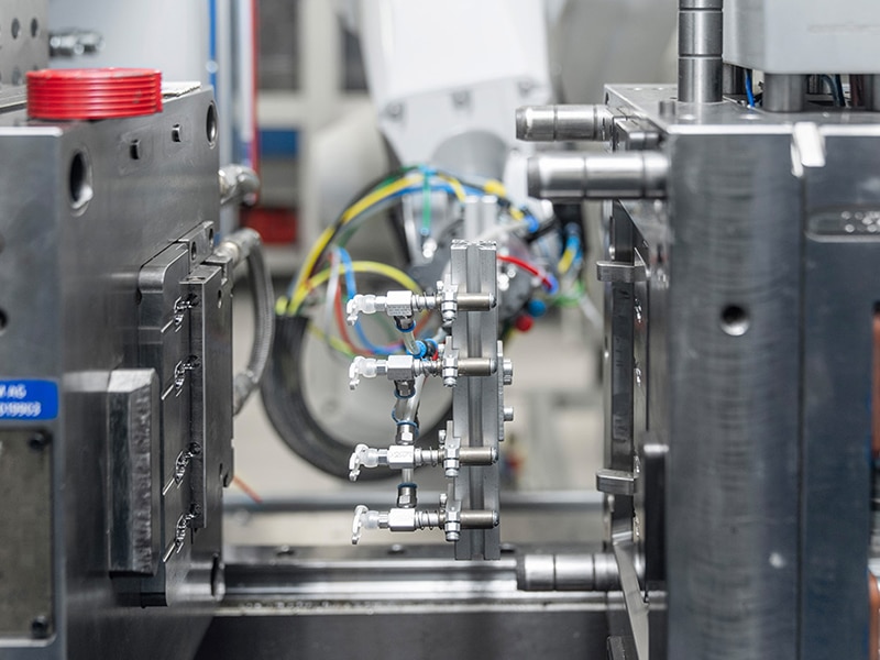
An injection mold ejection system is the part of the mold that separates a solidified part from the steel. The machine supplies the motion, and the ejection system turns that motion into a controlled push on the part. The system sits on the moving half, also called the ejector side. Plastic shrinks as it cools, so the part grips the core on that half. This placement lets the system push the part straight off the core.
What Does an Ejection System Do in Injection Molding
The ejection system does more than push a part out of the mold. Its work reaches the finished part and the molding process around it. The functions below explain what the system does.
- Release the part cleanly: The system pushes the part off the core or out of the cavity without damaging it.
- Protect surface and shape: The system spreads force across a wide area, so cosmetic faces stay clean and flat parts stay flat.
- Keep the cycle time stable: Reliable ejection lets the machine run without pauses because parts leave the mold without sticking.
- Keep gate areas clean: The system pulls the runner out together with the part. A clean release keeps the gate area intact, reducing drag marks and trimming defects.
- Prevent deformation: The system pushes at several strong points at the same speed, so thin walls and long ribs release without bowing or twisting, helping to ensure a close fit with the mating parts during assembly.
Ejection System Components and Their Roles
The ejection system includes several parts that work together. The table below gives a quick overview.
| Component | Role | Typical Material or Feature |
|---|---|---|
| Ejector pins | Push the part out of the core | Hardened tool steel, often nitrided |
| Ejector plate and retainer plate | Hold and move all pins together | Tool steel plates bolted together |
| Return pins | Push the plate back during mold closing | Hardened pins at the plate’s four corners |
| Sprue puller | Holds and ejects the sprue | Reverse-taper or Z-shaped head |
| Guide pins and bushings | Keep the ejector plate aligned | Hardened and ground |
| Stop buttons or pillars | Set the plate’s rear position and support the mold | Steel buttons or support pillars |
| Springs | Help the plate return in some designs | Heavy-duty die springs |

How the Ejection System Works in Injection Molding
Ejection begins once the part has cooled enough to hold its shape and the mold has opened. From there, a chain of movements takes the part off the core and resets the mold.
- The mold opens along the parting line. The part stays on the moving half because it shrinks onto the core.
- The machine pushes its ejector rod forward. The rod hits the ejector plate assembly inside the mold.
- The plate moves pins, sleeves, or blades forward through the core. These elements push the part off the steel.
- The part drops into a bin, or a robot picks it up.
- The mold closes. Return pins push the ejector plate back before the two halves meet.
Types of Ejection Systems in Injection Molding
Ejection systems differ in how they apply force to the part and in which part shapes they suit. The types below cover the most common choices in injection molds.
Ejector Pin Systems
Pin-based ejection systems are the most common option. Round pins slide through holes in the core and push the part at selected points. The layout places pins under ribs, bosses, and thick sections because these stiffer areas resist the push without denting or cracking. They cost less than other types, and a worn pin can be replaced on its own.
Sleeve Ejector Systems
A sleeve ejector is a hollow tube that wraps around a fixed core pin. It pushes the part around a hole or boss, so the force spreads evenly around that feature. This type suits ejecting parts with central holes or cylindrical features. Its design costs more than a plain pin, because the sleeve and core pin need tight, concentric fits.

Blade Ejector Systems
A blade ejector is a thin, flat pin that reaches narrow ribs where round pins cannot fit. The flat shape gives a larger contact area, so the pressure on the part stays lower. The blade is slender, so its thickness and guidance need care to prevent bending. The slot usually comes from wire EDM, which costs more than pin ejection.

Stripper Plate Systems
A stripper plate surrounds the core and pushes against the full rim of the part. Force spreads over a large area, so the part comes off without pin marks. This type suits thin-wall cups, rings, and round parts with tall walls. The plate must fit the core closely to block flash, and that fit wears over time.

Air and Valve Ejection
Air ejection uses a poppet valve at the tip of the core. When the stroke starts, the valve opens and air flows between the part and the core. The air breaks the vacuum behind deep, smooth, or soft parts. It can help overcome vacuum-related sticking. It is often used for large components with extensive core contact.
Two-Stage Ejection
Two-stage ejection moves the part in two steps. The first step breaks the grip in a tight area, and the second step completes the push. This type suits the ejection of parts that a single stroke would stress. This type adds moving parts, so cost and maintenance rise with the complexity.
Lifter Systems
A lifter is an angled rod that connects to the ejector plate. As the plate advances, the lifter moves forward and slightly sideways, which frees an undercut on the inside of the part. This type suits the ejection of parts with internal undercuts, such as snap-fit hooks and clips on housings and covers. Its sliding surfaces wear, so they need regular cleaning and lubrication.
Hydraulic and Pneumatic Ejection Systems
Hydraulic and pneumatic systems use a cylinder on the mold to drive the ejector plate, so the push no longer depends on the machine’s ejector rod. A hydraulic cylinder delivers high force with controlled speed, which suits parts that need a long stroke or a strong push. A pneumatic cylinder delivers lower force at a higher speed, which suits small, light parts. Both types need supply lines and regular leak checks.