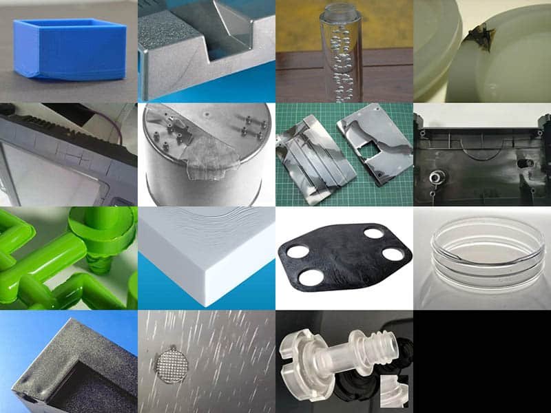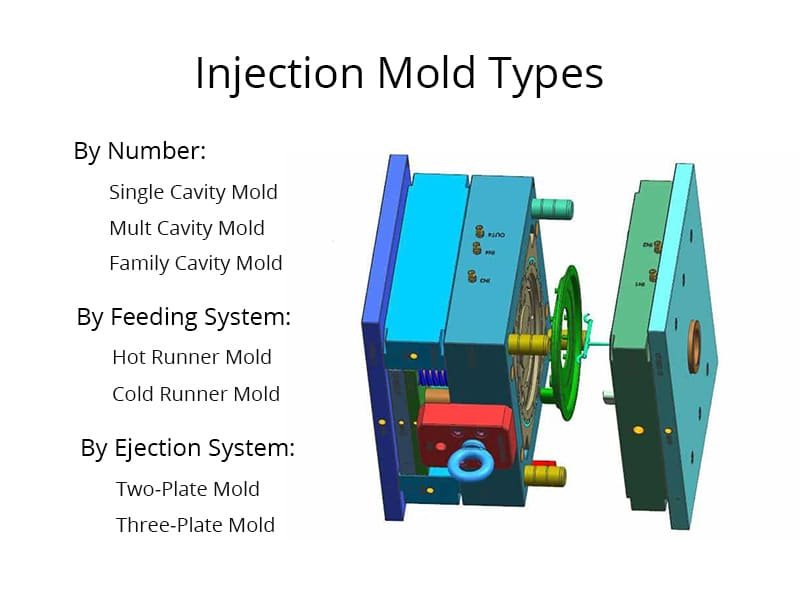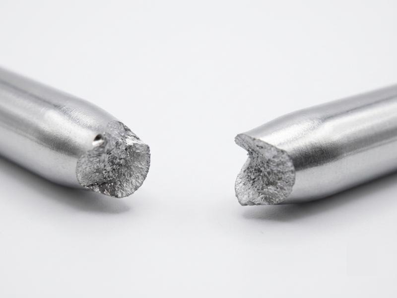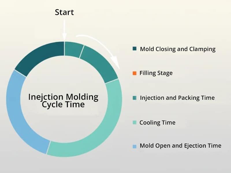

In plastic part design for injection molding, corner geometry is an important DFM consideration because it can restrict material flow and create areas of concentrated stress, which may lead to filling difficulties, warpage, or cracking during and after molding. For this reason, sharp corners, right angles, and notches should be avoided wherever possible, especially at wall junctions, along the direction of plastic melt flow, and where walls connect with reinforcing ribs, snaps, or bosses. Instead, these areas should use rounded transitions with appropriate radii. Proper corner design helps promote smoother material flow, distribute stress more evenly, and improve overall part integrity.
Factors Influencing Corner Design in Injection Molding
The design of corners in injection molding is not as straightforward as simply replacing sharp corners with rounded ones. Several factors impact the choice of corner radius and its effectiveness, making it crucial to balance various design elements. These factors include material selection, wall thickness, and part geometry.
1. Material Selection
Different plastics have varying characteristics, and some materials are more forgiving of sharp corners than others. Some polymers, like certain low-viscosity thermoplastics, can flow well through sharp corners during injection molding, reducing the impact of sharp corners. On the other hand, more viscous materials may experience flow restrictions at sharp corners, leading to incomplete fill and defects. Therefore, when designing plastic parts, it’s crucial to select a material that is suitable for the part’s geometry and manufacturing process.
2. Wall Thickness
Another factor that plays a role in corner design is wall thickness. Increasing the thickness of the walls near the corners can absorb some of the stress that would otherwise be concentrated at sharp corners. However, this solution often introduces its own set of problems, such as uneven cooling rates or the potential for sink marks. Balancing the wall thickness and corner radius is essential to avoid these issues and ensure the part maintains uniformity and strength.
3. Part Geometry
The shape of the part also influences how corners should be designed. Some parts are inherently easier to mold with sharp corners, while others, due to their complex geometries, require a larger radius. For example, intricate designs with deep pockets or sharp bends may require larger corner radii to ensure that the mold fills properly and that the part achieves the desired strength.
Why Sharp Corners Should Be Avoided
Sharp corners in injection molded parts are problematic for several reasons that affect both the manufacturing process and the end product. In injection molding corner design, eliminating sharp corners is a standard practice to ensure reliable outcomes.
1. Flow Impediment
In the injection molding process, the molten plastic must flow smoothly into every cavity of the mold. Sharp corners can restrict the flow, causing incomplete filling, short shots, or uneven material distribution. When the material cannot flow smoothly into sharp corners, it can also lead to air traps, which are pockets of air that form during the injection process. These air traps create defects on the part surface and can lead to poor cosmetic appearance and functional issues.
2. Stress Concentration
Sharp corners are areas where stresses concentrate, weakening the part’s overall strength. When a part is subjected to mechanical forces, sharp corners act as stress risers, which increases the likelihood of cracking or breaking under load. By transitioning sharp corners into rounded radii, the stress is more evenly distributed across the part, reducing the risk of failure under impact or fatigue.
3. Increased Risk of Part Failure
Because sharp corners are prone to stress concentration, they significantly increase the risk of part failure. This issue becomes even more critical in parts that will be exposed to dynamic loads, vibrations, or thermal cycling. The sharp corners act as weak points in the part, and under repeated stress, the material can fail. Rounded corners, however, reduce the likelihood of such failures, ensuring the part is more durable and reliable.
Design Considerations for Corners
1. Avoid Sharp External Corners (Except at Parting Lines)
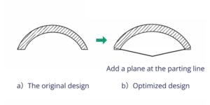
External sharp corners on the part surface generally require radii to improve flow and appearance.
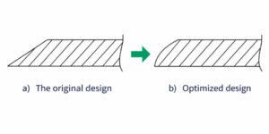
However, exceptions exist at the parting line, where the two halves of the mold meet. At this location, a sharp corner is often preferable because adding a radius can complicate the mold structure, increase costs, and lead to mismatches or steps on the part surface that affect aesthetics. In such cases, maintaining a straight edge at the parting line simplifies manufacturing.
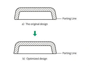
If a transition is needed near external connections, a short flat section of about 1.5 mm can be incorporated to facilitate the removal of flash or gate remnants, though this is less critical in standard injection-molded parts.
2. Corners Along the Melt Flow Path
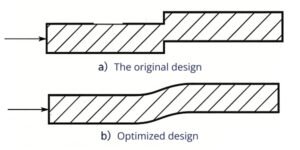
Corners that sit in the path of the plastic melt need their own design logic. The flow path, indicated by arrows in design diagrams, should remain unobstructed. Sharp corners in these areas can trap air, cause localized overheating, and result in material degradation or surface imperfections. Rounding these corners helps ensure even filling and reduce defects, promoting laminar flow. This is especially important in parts with intricate channels or multiple flow paths.
3. Corners at Wall Junctions (Inner Radius 0.3T < R < 0.8T)
Wall junctions, including connections between main walls and side walls, walls and ribs, or walls and bosses, are the most common place where corner design gets overlooked. Sharp internal corners at these junctions are prone to stress concentration, which can lead to part failure under load. The relationship between the internal fillet radius and the stress concentration factor is shown in the following figure. Where T is the wall thickness, R is the internal fillet radius, and p is the load borne by the part.
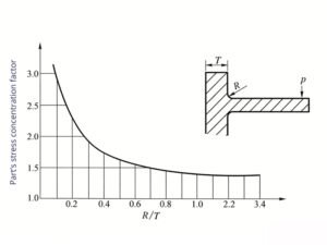
When R < 0.3T, the stress increases sharply; when R > 0.8T, stress concentration is essentially absent.
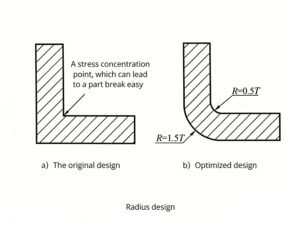
Generally, the inner fillet radius (R) at the joint of a part’s cross-section is 0.5T, and the outer fillet radius is 1.5T. This ensures uniform wall thickness and reduces stress concentration at the joint, as shown in the following figure. However, the fillet radius should not be too large, otherwise it may cause excessive local wall thickness, resulting in shrinkage.
Conclusion
Injection molding corner design, with a focus on avoiding sharp corners, is essential for successful plastic part manufacturing. By addressing the factors of material, wall thickness, and geometry, applying targeted guidelines becomes a standard part of meeting DFM requirements. This results in fewer defects, improved strength, and reliable performance. Adhering to these principles in corner design supports the creation of high-quality injection-molded parts. As a professional injection molding manufacturer, Erye reviews part geometry, including corner and fillet design, as part of our design and manufacturability checks for every project.