Injection molding mold parts, ranging from the mold base structure to the ejection system, work in harmony to produce intricate plastic parts with high precision. In this article, let’s delve into the critical components of injection molds, exploring their materials, manufacturing processes, and maintenance tips for achieving optimal results in the molding process.
The Seven Major Systems in Plastic Injection Mold
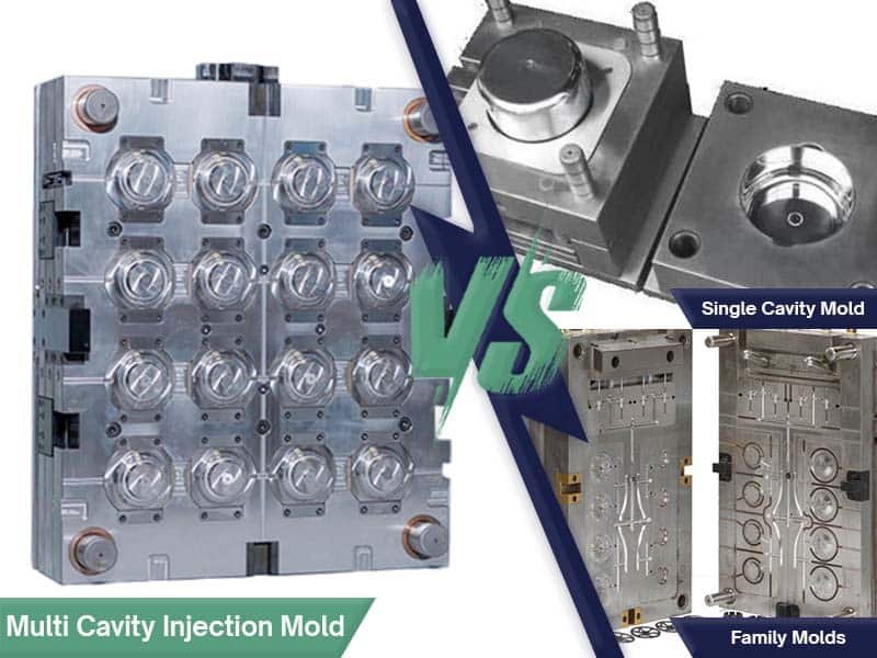
There are 8 common types of injection molds; however, each type consists of similar key components. These components fall into seven major systems, each responsible for a specific function that collectively shapes the final molded part. Below is an overview of these critical systems:
An injection mold consists of seven major systems that work in concert to produce high-quality plastic parts.
- Clamping system: holds the mold halves together with immense force, ensuring a secure environment for the injection process.
- Feed system: so so-called injection system, injects molten plastic material into the mold cavity.
- Cooling system: rapidly cools the plastic, solidifying it into the desired shape.
- Ejection system: then carefully removes the solidified part from the mold.
- Guiding system: comprised of guide pins and bushings, ensures precise alignment between the mold halves.
- Venting system: allows for the escape of air and gases during injection, preventing voids and ensuring complete filling of the cavity.
- Molding parts system: encompassing the cavity and core, defines the shape and features of the final product.

These seven systems interact intricately, with each playing a critical role in achieving optimal part quality, cycle times, and overall production efficiency. Following, let’s look deeper into each part of an injection mold
Mold Base Structure
The mold base structure forms the foundation of an injection mold, providing the necessary support and housing for the mold components. It ensures that all the mold parts align correctly and function together during the injection molding process. The mold base consists of several key components that are designed to work in unison for maximum efficiency and precision. These components include the clamp plate, A plate, B plate, spacer block, and cavity retaining plate.

Clamp Plate
The clamp plate is a critical component in the mold base structure, designed to hold the mold halves together during the injection molding process. It is subjected to high pressure and forces when the mold is clamped shut to allow the molten material to be injected into the cavity. The clamp plate provides the necessary rigidity to maintain proper alignment and prevent any misalignment between the mold halves during operation. The clamp plate is typically made from high-strength materials like steel or aluminum to withstand the forces involved in the molding process.
A Plate
The A plate is the first part of the mold assembly and is located on the side of the mold that holds the cavity. It is typically a solid plate that houses the mold components such as the mold cavity and part of the cooling and heating systems. The A plate is designed to provide a surface for the injection nozzle to connect, allowing the molten plastic to flow into the mold cavity. It also serves as the base for the mold’s guiding system, which ensures accurate alignment between the core and cavity plates.
B Plate
The B plate is the opposite side of the A plate and holds the mold’s core and ejection components. It’s often referred to as the “core side” of the mold. The B plate is typically a thicker plate that houses the ejection pins, lifters, slides, and any other components that help eject the molded part once it is solidified. The B plate’s function is crucial for the proper ejection of the part without damaging the mold or the molded part itself.
Spacer Block (C Plate)
The spacer block, also known as the C plate, is used to maintain the correct distance between the A plate and B plate. It ensures that the mold components align properly when the mold is closed, providing the required gap between the mold halves to allow for efficient plastic injection. The spacer block is a vital part of the mold structure, ensuring the mold can operate smoothly and produce parts of high quality.
Cavity Retaining Plate
The cavity retaining plate secures the mold cavity within the mold base structure. It is typically found on the A plate and works in tandem with the A plate to hold the cavity in place during the injection process. This plate is designed to ensure the cavity does not shift or move during the molding process, which could result in a misaligned or defective part. It also plays an important role in ensuring that the cavity is properly cooled and heated.
Feeding System
The feeding system is designed to guide the molten plastic into the mold cavity. It includes the sprue, runner, and gate, which together ensure that the material flows correctly into the mold. Each part of the feeding system must be carefully designed to avoid material waste, reduce cycle time, and ensure consistent part quality.
The figure below shows that at Runners 1 and 2, if the design is not completely symmetrical, it can lead to uneven injection pressure across the mulit-cavities. If dimensional tolerances of the part are lenient, this might be acceptable; however, for high-precision products, a fully symmetrical design is required to ensure uniformity. Otherwise, molding defects such as warpage, flash, and short shots are likely to occur.
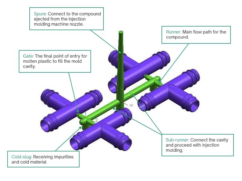
Sprue
The sprue is the initial channel that conveys molten plastic into the mold. It connects the injection molding machine nozzle to the runner system. Once molten plastic is injected into the sprue, it flows into the runner and gate systems, filling the mold cavity. The size and design of the sprue are critical for ensuring that the flow of molten plastic is smooth and uniform, preventing issues such as air pockets or insufficient filling.
Runner
The runner is a channel that distributes molten plastic from the sprue to the mold cavity. In multi-cavity molds, the runner divides the material flow into several sub-runners.
If the runner cross-section is too small, mold filling time increases, pressure loss rises, and defects such as short shots, burn marks, and sink marks may occur. Conversely, an excessively large cross-section increases the amount of recondensed material and prolongs cooling time.
Gate
The gate is the final point where the molten plastic enters the mold cavity. Gates are designed to control the flow of material into the mold and ensure that the cavity is filled evenly. The design and placement of the gate are crucial for achieving optimal part quality. Poorly designed gates can lead to cosmetic and performance issues during demolding. Different types of gates can be used, such as pin gates, edge gates, and submarine gates.
Read our blog Injection Molding Gate: Types, Locations, and Best Practices
Cold Slug Well
A cold slug well is a small cavity integrated near the end of the runner or adjacent to the gate. Its purpose is to trap solidified “cold slugs” — pieces of polymer that chill and solidify in the nozzle or runner — preventing them from entering the mold cavities and causing defects. If these cold slugs infiltrate the cavity, they can cause surface blemishes, knit lines, incomplete filling, or degraded mechanical performance
Molding System
The molding system includes the core and cavity, which together shape the molded part. The core forms the interior features of the part, while the cavity forms the exterior shape. Other important components of the molding system include slides, lifters, and inserts, all of which assist in creating more complex shapes and features.
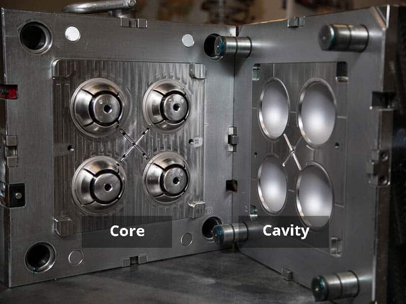
Mold Cavity
The mold cavity is the hollow section of the mold that gives the part its shape. It is typically designed to match the exterior geometry of the final product. The cavity is created by the mold halves coming together during the injection molding process. The quality and design of the mold cavity are crucial to producing parts with consistent dimensions and smooth surface finishes.
Mold Core
The mold core is the counterpart to the cavity, forming the interior features of the molded part. It is designed to create holes, indentations, or other features that are required inside the part. In many cases, the core is made of a different material than the cavity to ensure that it can withstand the pressure and heat of the injection process. Cores are also frequently designed to be removable or adjustable, depending on the complexity of the part.
Slides or Sliders
Slides or sliders are components that are used to form undercuts or other complex features within the mold. These moving parts are attached to the mold base and are used to create geometries that would be difficult to form with a standard cavity and core. Slides and sliders move in a specific direction during the molding cycle to allow the part to be ejected without damage.
Lifters
Lifters are components used to lift or move parts of the molded piece out of the mold cavity. They are often used in parts with complex geometries or undercuts, where the part cannot be removed in a straight line. Lifters are activated by the mold’s ejection system, helping to push the part from the mold cavity without causing damage to the part or the mold itself.
Inserts
Inserts are used to create more detailed features within the molded part or to insert additional components into the molding process. Inserts can be made of metal or plastic and are placed within the mold before the injection of the molten plastic. This allows the plastic to flow around the insert and form a strong bond. Inserts can be used to reinforce the part, add threads, or create specialized features that would be difficult to form with the mold alone.
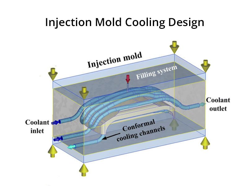
Cooling System

The cooling system plays a critical role in the injection molding process by regulating the temperature of the mold. Once the molten plastic is injected into the mold cavity, it must cool and solidify to take the desired shape. An efficient cooling system ensures the mold stays within the optimal temperature range, preventing overheating or excessive cooling, both of which can affect part quality and cycle times. A well-designed cooling system is crucial for improving production efficiency and reducing the time needed for each molding cycle.
Guiding System
The guiding system is essential for ensuring that all components of the mold align correctly during the injection process. The primary purpose of this system is to maintain accurate alignment of the moving parts within the mold, which prevents issues like misalignment, excessive wear, or part defects. This alignment is particularly important during the closing and ejection phases of the molding process, where precision is key to achieving the desired results.
Guide Pins
Guide pins are one of the most critical components of the guiding system. These pins allow the moving parts of the mold to align and move smoothly along the mold base. When the mold closes, guide pins ensure that the cavity and core plates fit together precisely, creating the correct part shape. They are typically made of high-strength steel to withstand the repeated forces applied during the injection process.
Guide Bushing
Guide bushings are paired with guide pins to help stabilize and guide the mold’s moving components. They are usually installed in the mold base and work in conjunction with guide pins to ensure smooth, precise movement. The bushing provides a stable contact point for the guide pin, minimizing wear and tear and improving the mold’s overall longevity. It also ensures that the mold components move without excessive friction, which can affect the injection process.
Ejection System
The ejection system is responsible for safely removing the molded part from the mold once it has cooled and solidified. This system must be designed to handle the ejection force without damaging the mold or the finished part. It’s particularly crucial when dealing with intricate or complex parts, where a gentle and uniform ejection process is necessary to avoid deformities or defects.
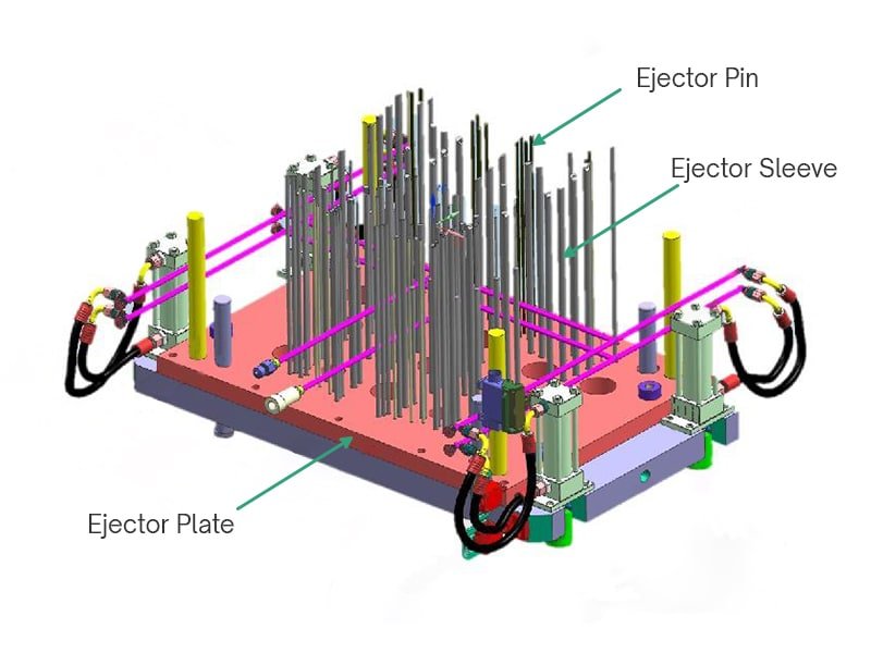
Ejector Plate
The ejector plate is a key component in the ejection system, typically located on the rear of the mold. This plate is attached to a set of ejector pins and is responsible for pushing the molded part out of the cavity. The ejector plate moves forward to push the part out once the injection process is complete, and the mold is open.
Ejector Pin
Ejector pins are used in conjunction with the ejector plate to push the molded part from the mold cavity. They are strategically placed to ensure that the part is ejected evenly and without damage. The placement and number of ejector pins can vary based on the complexity and size of the molded part. These pins are typically made of durable materials such as steel or nitrided steel to resist wear and tear during repeated use.
Ejector Sleeves
Ejector sleeves surround the ejector pins and provide a secure pathway for them to eject the molded part. These sleeves protect the ejector pins from friction and wear by reducing direct contact with the part itself. They also help ensure that the pins are aligned correctly during the ejection process, preventing the molded part from becoming damaged or deformed. Ejector sleeves are an essential component when the mold design requires precise pin placement and alignment.
Venting System
The venting system is designed to allow air and gases to escape from the mold cavity during the injection process. If air is trapped inside the cavity, it can lead to defects such as air pockets or voids in the finished part. The venting system ensures that the cavity fills correctly and that any trapped air is expelled, preventing mold imperfections. Venting systems are particularly important for molds with intricate designs or deep cavities, where air might otherwise become trapped. Proper venting improves the overall efficiency of the molding process by reducing cycle time and increasing part quality.
By understanding the role of each of these mold parts and systems, manufacturers can optimize their injection molding process for improved part accuracy, efficiency, and quality. Every component of the mold serves a specific purpose, and the success of the injection molding process depends on how well these parts work together.
Materials Used in Plastic Mold Components
Choosing the right material for each mold part is critical to ensure the injection molding process runs smoothly, efficiently, and produces high-quality parts. The right material choices also affect factors like wear resistance, heat resistance, and ease of maintenance.
Commonly Used Materials for Mold Components: Steel, Aluminum, etc.
Mold components are made from a variety of materials, each selected for its unique properties that meet specific requirements in the injection molding process. The most common materials used are steel and aluminum, but other materials may also be used depending on the application.
- Steel: Steel molds are highly suitable for high-volume production, as they can withstand the repeated stress and wear of multiple molding cycles. Steel alloys like P20, H13, and S7 are commonly used in various components like the core, cavity, and inserts. Steel molds are more expensive than aluminum molds, but are ideal for long-term and high-volume production runs.
- Aluminum: Aluminum is an ideal choice for prototypes and low-volume production. Aluminum molds are also more affordable than steel molds and are known for better heat transfer properties, which can reduce cycle times. However, they are less durable than steel and may not be suitable for long-term or high-volume production. Common grades of aluminum used in mold making include 7075 and 6061.
Material Selection Criteria Based on Part Requirements
Selecting the right material for mold components requires careful consideration of various factors, such as:
- Part Geometry: Complex parts with intricate designs may require more specialized materials, such as those with excellent thermal conductivity or enhanced durability.
- Production Volume: High-volume production molds benefit from materials with greater longevity and strength, like steel. For smaller production runs, cost-effective materials like aluminum might be more appropriate.
- Heat Resistance: Parts exposed to high temperatures during the molding process require mold materials with good thermal stability, such as high-carbon steel or heat-treated alloys.
- Wear Resistance: For molds that will produce thousands or millions of parts, wear resistance is crucial. Materials with high hardness and toughness, like tool steels, are selected for components exposed to wear.
- Corrosion Resistance: Molds used for producing parts with aggressive chemicals or in corrosive environments should be made from materials with good corrosion resistance, such as stainless steel.
Manufacturing Processes for Injection Mold Components
The manufacturing of injection mold components requires high precision to ensure that each part fits and functions properly. Various manufacturing processes are used to create the mold components, each suited to specific tasks and desired tolerances.
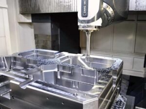
CNC Machining for High Precision
CNC (Computer Numerical Control) machining provides high precision and allows for the creation of complex geometries with tight tolerances. CNC machining is often used for creating mold cavities, cores, and other key components like inserts, slides, and pins. The use of CNC machining ensures that mold parts are produced with high accuracy, minimizing defects and improving the quality of the final molded parts.
Electrical Discharge Machining (EDM) in Mold Making
EDM is a specialized machining process used to create intricate shapes in mold components, especially those made of hard materials like steel. This process allows for the precise cutting of complex geometries that may be difficult to achieve through traditional machining methods. EDM is particularly useful for creating small, detailed features like holes, slots, and contours in mold cavities and cores. It is often used in conjunction with CNC machining to achieve the desired mold features.

Tips for Optimizing Mold Performance
Optimizing mold performance involves maintaining high efficiency throughout the mold’s life cycle. This includes regular maintenance, improvements to cooling efficiency, and minimizing downtime.
Regular Maintenance of Components
Routine maintenance is essential to keep mold components in peak condition. This includes cleaning and lubricating moving parts like ejector pins, slides, and cores. Regular maintenance helps prevent corrosion, wear, and tear, extending the mold’s lifespan and preventing costly breakdowns. Mold components should be inspected regularly for damage or wear, and any issues should be addressed promptly to avoid disruptions in production.
Enhancing Cooling Efficiency
Efficient cooling is essential to minimize cycle times and ensure high-quality molded parts. Mold cooling systems should be carefully designed and maintained, ensuring that cooling channels are unobstructed and function as intended. By optimizing the cooling system, manufacturers can significantly reduce cycle times, improve part consistency, and extend the mold’s lifespan.
Minimizing Downtime Through Effective Repairs
Unscheduled downtime can result in significant costs, both in terms of lost production and repairs. A proactive approach to identifying potential issues in mold components, such as worn ejector pins or damaged cooling channels, can help minimize downtime. Quick repairs and part replacements are essential for maintaining production schedules and ensuring mold performance.
Conclusion
Injection molds are made up of a variety of components, each serving a specific function in the molding process. The mold base structure, feeding system, molding system, cooling system, guiding system, ejection system, and venting system all work in unison to create high-quality molded parts.
The design of mold components directly impacts the quality of the final molded parts. High-quality materials and precision manufacturing processes result in molds that can produce parts with tight tolerances, consistent dimensions, and minimal defects.