Screw boss is an indispensable feature that impacts functionality, strength, and manufacturability of injection molding parts. These cylindrical protrusions often refer to bosses in plastic design, which play a vital role in assembly and attachment, accommodating screws, threaded inserts, and other fasteners.
This article provides a comprehensive guide on plastic boss design, covering their purpose, applications, design guidelines, challenges, and solutions.
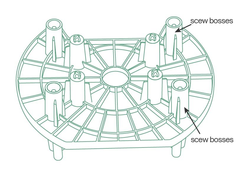
What Are Screw Bosses in Injection Molding?
Screw bosses are protrusions on plastic parts used to enhance assembly by guiding and positioning components, providing structural support, and securing them in place. These features are crucial for ensuring parts fit together correctly and maintain integrity during use.
Purpose of bosses in plastic design
- Provide strong attachment points for secure fastening in multi-part assemblies.
- Reinforce local areas to improve structural strength and distribute mechanical loads.
- Maintain precise alignment between mating parts during assembly.
- Function as bearing seats or mechanical pivots within the design in some cases
When to use a plastic boss
- Anchoring screws or inserts under torque
- Aligning and joining enclosure parts
- Mounting internal components
- Reinforcing thin-wall areas
- Controlling assembly tolerances
Consideration Factor for Screw Boss Design
There are several factors to consider when designing screw bosses for an injection molded parts. The design should ensure the parts perform as intended and are manufacturable without defects. Key factors to consider include:
Part Strength
Screw bosses must withstand continuous stresses imposed by screws or fasteners without cracking or deforming. It is recommended to avoid placing a screw boss chose to an external wall.
Consider reinforcing the screw boss with gussets or ribs to improve the strength of the screw boss. To increase part strength, read our previous blog: How to Design Stronger Plastic Parts.
Material Type
For the plastic boss design part, plastic materials with uniform shrinkage are preferred. As they offer superior dimensional accuracy. Choose materials soft and brittle, as they can accept screws easily. If you choose brittle plastics like polystyrene may require thicker walls to prevent fracture. In the other case, if you choose polycarbonate for molding, which is primarily a brittle plastic, the best approach should be to blend it with a softer material such as ABS.
Assembly Requirements
The screw boss must be designed to fit the specific fastener being used, considering factors such as screw size, thread type, and required depth of engagement.
Design Guidelines for Bosses in Plastic Design
The following highlights 10 simple plastic boss design guidelines. Adhering to these basic guidelines for injection molded parts can improve the moldability of the designs and increase the operational lifespan of the parts.
Location of the Screw Boss
Position bosses in thicker wall regions or primary load paths to ensure mechanical support. Avoid placing them in thin walls, sharp corners, or zones prone to stress concentration. Tie bosses into the surrounding structure with ribs or gussets for load distribution and moldability benefits. The following areas are recommended:
- Thick Wall Areas: Installed screw bosses on the thicker section of the part to provide firm fastening and stability.
- Stress Areas: Position bosses within the main stress areas of the part to enhance overall strength and stability. Avoid placing them on thin arcs or weak walls.
- Distribution: Distribute screw bosses evenly across different sides of the parts to maintain balance and stability during assembly and use.
- Interior Placement: Locate bosses on the interior of the part rather than the exterior to protect them from external damage.
Wall Thickness
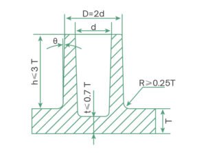
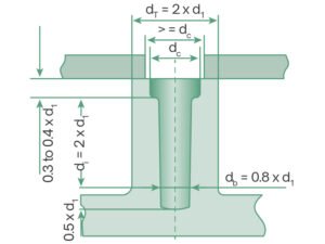
To avoid surface sink marks and air bubbles, keep the screw boss thickness at no more than 60% of the part’s nominal wall thickness (T). Also, it’s common for the outer diameter to be twice the inner diameter, ensuring structural strength. For thin-wall parts, read our guide on thin-wall injection molding design guide.
Boss Height to OD Ratio
If the screw boss is too tall, due to the presence of the draft angle, the top dimension will be smaller, making injection molding difficult. If the top dimension is maintained, it will result in a thicker base, causing surface sink marks and air bubbles. Therefore, the height of the screw boss should generally not exceed 3 times the nominal wall thickness of the part, i.e., h≤3T。
Minimize Radius at Base of the Screw Boss
To reduce stress and ensure smooth plastic flow, the fillet radius at the base should be between 0.25~0.50 times the nominal wall thickness (R = 0.25T ~ 0.50T). Also, keep the base thickness at no more than 70% of the nominal wall thickness (t ≤ 0.7T) to avoid visible sink marks.
Draft Angle Incorporation
Typically, use a 0.25° draft angle for the inner diameter and 0.5° for the outer diameter for easy demolding. In some cases, you might skip the draft angle, for example, by using a sleeve in the mold for ejection, but this can increase the mold costs.
Standalone Bosses
To prevent the design of isolated screw bosses, it is recommended to integrate them with the part wall using reinforcing ribs, forming a cohesive structural unit
Standalone screw bosses can weaken plastic parts if not properly supported. Connecting them to the part wall with ribs strengthens them and aids plastic flow during molding.
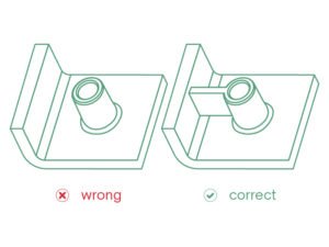
When a screw boss is positioned near the gate area, bosses risk forming weld lines, which reduce strength, especially for self-tapping screws or metal inserts. Ribs should be added around standalone screw bosses to help mitigate these issues. Additionally, incorporating fillets at the junctions between ribs and bosses helps distribute stress evenly and enhances durability.
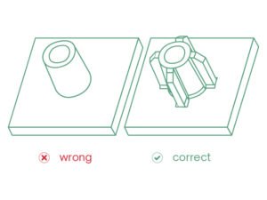
Maintaining Uniform Wall Thickness
A fundamental principle in plastic boss design is to maintain uniform wall thickness to avoid molding defects. When bosses are placed too close to the part walls can cause thick sections, leading to sink marks and air bubbles.
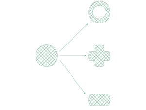
Solid plastic bosses can be redesigned as hollow, cross-shaped, or elliptical to maintain consistency and avoid defects. This can reduce material volume and prevent cooling-related issues.
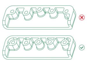
Spacing Between Bosses
To avoid defects like sink marks, it is recommended to maintain a minimum spacing of twice the nominal wall thickness between screw bosses. This ensures proper cooling and prevents thin areas that could extend cycle times or compromise part quality.
Standardizing Screw Boss Design
For bosses used with self-tapping screws, adhering to standard hole designs is recommended. This ensures reliable assembly and reduces errors, avoiding the need for unconventional approaches that may introduce risks.
Material and Thickness Selection
Use the same material for the plastic boss as the rest of the injection-molded part to maintain uniform properties and avoid differential shrinkage. The following table lists the ideal thickness of some of the most popular injection molding materials.