Gas mark in injection moulding is a defect that appears on the gate area or locally on the surface of the product, affecting its overall appearance.
While gas marks do not significantly impact the product’s safety or functionality and are considered minor defects, they do affect the aesthetic quality of the product’s surface, thereby influencing user satisfaction and the product’s appearance. Typically, such defects are not acceptable.
Causes and Solutions of Gas Mark in Injection Moulding
Uneven and Excessive Wall Thickness
Uneven wall thickness can lead to differential cooling rates, causing flow lines and potentially trapping gases. Thick walls, especially, can result in slower cooling, allowing gases to be trapped and emerge as defects.
Excessively thick sections can lead to gas traps, as the inner material remains molten longer, potentially compressing gases and causing surface defects like gas marks.
Solution
To reduce gas marks in injection moulding defects, the common solution is to adjust the wall thickness to ensure uniformity.
To design thin-wall injection molding parts, read our guide on thin-wall injection molding design tips
Complex Structures and Improper Rib Placement
Complex structures can create areas where gases are trapped, especially if venting is inadequate. Improper rib placement can exacerbate gas mark defects by creating flow restrictions, leading to air traps. Complex designs and poorly placed ribs hinder gas expulsion, contributing to defects.
Solution
Simplifying the structure, including optimizing rib design, helps improve mold filling and gas expulsion.
Inappropriate Material Selection
Selecting a material with poor flowability or insufficient lubricant content can lead to the appearance of gas marks. (Do you know the 6 common mistakes in plastic material selection?)
Materials with poor flowability can lead to incomplete mold filling, trapping gases, and causing surface defects like gas marks. Low flowability increases resistance during filling, potentially trapping air or gases, leading to visible marks. For instance, materials with a low melt flow index (MFI) may struggle to fill complex molds, exacerbating gas entrapment.
Internal lubricants, such as fatty acid esters (e.g., glyceryl monostearate), are additives that reduce viscosity, improving the material’s flow properties. Insufficient lubricant content can result in higher viscosity, making it harder for the material to flow smoothly and expel gases. Lubricants help reduce friction between resin molecular chains, facilitating better mold filling and reducing defect formation.
Solution
To address this, consider opting for materials with better flowability or incorporating additional processing aids. Selecting materials with higher MFI, such as certain grades of nylon or ABS, can improve flow and reduce defects. Additionally, increasing the lubricant content in the material can enhance flowability.
Improper Gate Design
If the gate is too small, it restricts the flow of the material, leading to slower filling speeds. Slow filling allows gases to become trapped, as there is insufficient force to push them out of the mold. Additionally, an improperly positioned gate can direct the flow in a way that traps gases in certain areas of the mold, particularly in complex geometries or areas far from the gate.
Solution
To fix this, it is suggested to increase the size of the gate and runner to improve flow and change the gate’s position for better gas expulsion.
Repositioning the gate to a location that promotes better flow and venting. For example, placing the gate at the thickest section of the part can ensure that the material fills the mold in a way that pushes gases towards the vents. In some cases, multiple gates may be used for larger or more complex parts to ensure even filling and gas expulsion.
We have summarized 12 types of gates. Read our blog to learn types of injection molding gates and how to choose.
Injection Molding Process Issues
Low injection pressure, slow injection speed, and short injection time can trap gases inside the mold, causing gas marks.
Low injection pressure may not force the material to fill the mold completely, leaving areas where gases can be trapped. Slow injection speed can allow gases to be trapped as the material flows slowly into the mold, as rapid filling helps to sweep gases towards the vents. Short injection time means the material may not have enough time to fill the mold completely, again leading to gas entrapment.
Solution
Increasing the pressure and speed, and extending the injection time, can help ensure the mold fills properly and gases escape.
Increasing the injection pressure ensures that the material fills the mold completely and pushes out any trapped gases. Extending the injection time allows for complete filling of the mold and better control over the flow, ensuring that gases have sufficient time to escape before the material solidifies. Holding pressure and time after injection helps to pack the material and expel remaining gases.
Unreasonable Temperature Setting
Material temperature and mold temperature are too high, causing the material to flow excessively well, which prevents gases from being expelled in time and results in gas marks.
Additionally, high temperatures can cause the plastic to degrade, releasing volatiles (such as moisture or decomposition gases) that contribute to gas marks. High mold temperature can also contribute to the material flowing too quickly, trapping gases, and can exacerbate the issue if the material temperature is also high. However, excessively low mold temperatures can lead to short shots or other defects.
Solution
Reducing the material and mold temperatures increases the viscosity of the plastic, slowing down the flow and allowing more time for gases to escape.
Each plastic material has a recommended processing temperature range, and operating within this range ensures that the material flows well without becoming too fluid or degrading.
Gas Mark in Injection Moulding Case Study
Project Introduction
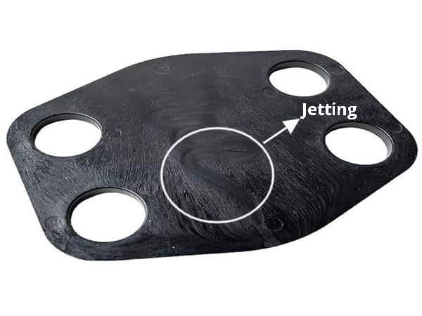
The figure illustrates an example of a gas mark that appears at the gate area. The injection molding part is made from ABS material, using a direct gate for material injection. It is not acceptable for the gas mark defect as it is an appearance-type product.

Injection molding parameters are as follows:
| Parameter | Value |
|---|---|
| Mold Temperature | 100℃ |
| Material Temperature | 210~240℃ |
| Injection Speed | First Stage 9mm/s; Second Stage 28mm/s; Third Stage 15mm/s |
| Injection Pressure | First Stage 90kgf/cm2; Second Stage 105kgf/cm2; Third Stage 80 kgf/cm2 |
| Injection Time | 13s |
How to Fix Gas Mark on Plastic
Cause Analysis
Judging from the molding parameters, our engineers found out that the first-stage injection speed is incorrect. It should be adjusted to a medium-low spped to completely fill the runner, followed by a low speed just before the molten plastic enters the mold cavity. After the cavity is filled with a small portion, the speed should be increased to high, and finally, switched back to low speed for the completion of injection. The injection molding process should be divided into four distinct stages.
Additionally, upon inspection by our engineers, they found that the gate size is too small. It is better to use a large gate to reduce the gas mark defect at the gate area.
Solutions
We take the following actions to fix the gas mark in injection molding
1. Adjusting Injection Speed
When setting the injection speed, ensure the corresponding injection pressure is high enough to achieve the desired speed. If the pressure is too low, the actual speed may be lower than the settled speed, even if the parameters seem correct.
2. Modifying the Mold
Enlarge both the injection mold gate and runner to improve material flow and reduce potential gas mark defects.
3. Increase Mold Temperature
Raise the mold temperature appropriately to help reduce internal stresses and improve the surface quality of the molded parts


