What is CNC Milling

cnc milling
In This Article
    Add a header to begin generating the table of contents
    Scroll to Top

    CNC milling is a subtractive manufacturing process controlled by computer numerical instructions. Because it can achieve precision consistently, it is the preferred process across industries from aerospace to medical devices, wherever a part’s fit and function depend on exact dimensions. This guide walks through how CNC milling works, its different types, and how to design parts that machine cleanly.

    What Is CNC Milling?

    CNC milling is one of the processes within CNC machining. Material is held stationary while a rotating cutting tool moves along a programmed toolpath, removing material from the stock step by step until form the final shape. It is opposite to CNC turning, where the workpiece itself spins against a stationary tool.
    Because the cutting process is precisely controlled, CNC milling can achieve tight tolerances, allowing CNC milling to be used for many types of parts, such as aluminum brackets, stainless steel housings, and custom fixtures.

    How Does CNC Milling Work?

    The process runs through a consistent sequence, regardless of part complexity or quantity.

    • Design and CAM programming: The process starts with a 3D model that defines the part geometry. CAM software converts the model into toolpaths with cutting paths, speeds, feeds, and tool selections.
    • Setup: A block of raw material is clamped into the machine, with the required tools loaded and the origin point set to establish the machining coordinates.
    • Machining: The spindle spins the cutting tool at high speed while it moves along the programmed path, cutting away material pass by pass, which is opposite to CNC turning.
    • Inspection: The finished part is measured against the drawing’s tolerances, usually with calipers, a CMM, or both.

    Take a custom electronics enclosure as an example. The CAM software plans a route that mills the outer pocket first, then drills the mounting holes, then cuts the cable cutout last. All the steps are completed within a single automated sequence.

    Inside a CNC Milling Machine

    A CNC mill relies on several key components that work together to position the cutting tool, secure the workpiece, and execute programmed movements.

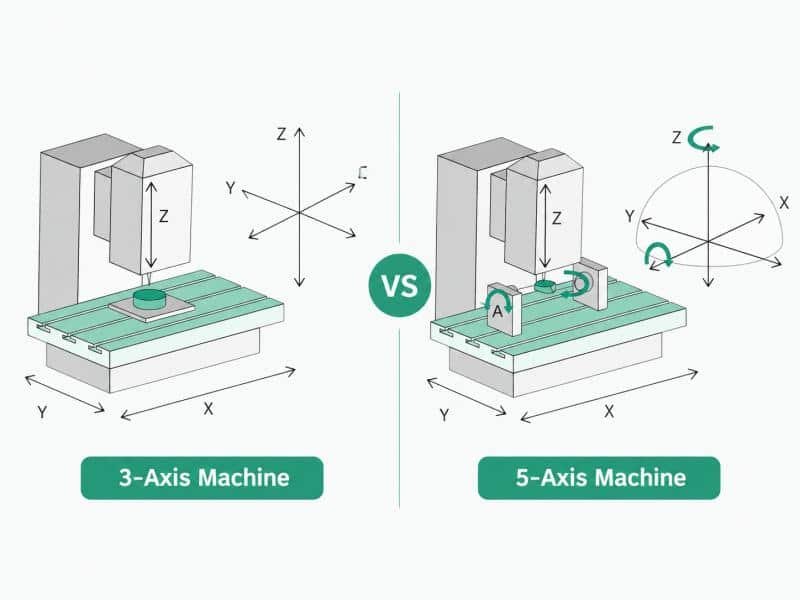
    • Machine Axes: Control the movement of the cutting tool or workpiece. Three-axis mills use X, Y, and Z movements, while multi-axis machines add rotation for more complex features.
    • Spindle: Holds and rotates the cutting tool at high speed. It moves the tool along the Z-axis while controlling the cutting speed and stability during machining.
    • Worktable: Secures the workpiece with a vise or fixture and typically moves along the X and Y axes to position different areas of the part under the rotating cutting tool.
    • Tool Changer: Automatically switches between tools for operations such as drilling, facing, and contouring.
    • Coolant System: Controls heat and removes chips during cutting to maintain tool life and surface quality.

    Common CNC Milling Machine Types

    CNC milling machines vary in their axis configuration and structure, which affects how the cutting tool approaches the workpiece, the features they can create, and the types of parts they are best suited for.

    • 3-axis mills move along X, Y, and Z. They are used for flat and moderately contoured parts and are usually the fastest, most economical option when the geometry allows it.
    • 4-axis mills add a rotational axis, allowing the workpiece to rotate so a fourth side can be machined without manual re-clamping. Useful for parts with features around a cylindrical body.
    • 5-axis mills add two rotational axes, letting the tool approach the part from nearly any angle in a single setup. They are used for complex, sculpted, or undercut geometry and are a common example of multi-axis CNC machining.
    • Vertical machining centers (VMCs) hold the spindle vertically, straight down onto the table. They are common, space-efficient, and well suited to plate-like or prismatic parts.
    • Horizontal machining centers (HMCs) hold the spindle sideways. Chips fall away from the part instead of collecting on it, which supports more efficient continuous machining.

    Choosing the Right Material for CNC Milling

    Material choice depends on how a part will be loaded, where it will operate, and how much it needs to weigh. The same geometry may need a different material depending on the following factors.

    Mechanical Requirements

    How much load, stress, or repeated cycling a part needs to withstand determines the minimum strength and fatigue resistance required. For example, a structural bracket that carries repeated vibration is often specified in 7075 aluminum rather than 6061. Although 7075 is more difficult to machine, its higher strength and fatigue resistance make it a better choice.

    Operating Environment

    Exposure to moisture, chemicals, temperature swings, or outdoor conditions favors materials with corrosion resistance or stability across a wider temperature range. A fixture used in a food-processing line is often specified in 316 stainless steel rather than a standard aluminum alloy, since it needs to hold up against repeated washdowns and cleaning chemicals.

    Machinability

    Harder materials remove more slowly and wear tools faster, pushing cost and time up. An easier-to-cut alternative is usually selected when requirements allow. For example, titanium is mechanically excellent for aerospace parts, but cuts far slower than aluminum, so aluminum is often chosen unless titanium’s strength or heat resistance is specifically needed.

    Surface and Finish Requirements

    Parts with sealing surfaces, cosmetic visibility, or specific texture may favor a material that finishes cleanly. For example, a decorative hardware component might use brass for its ability to take a polished or brushed finish directly off the machine, rather than a plastic that would need painting to achieve the same look.

    Types of CNC Milling Operations

    Different milling operations are used to create specific features on a part, depending on its geometry and design requirements.

    • Face milling: The cutter axis is perpendicular to the workpiece surface, and material is removed by the tool’s face to create a flat reference surface.
    Face Milling
    Face Milling
    • Plain milling: The cutter axis runs parallel to the workpiece surface, and the tool removes material by its circumference, making it suitable for roughing operations before finer finishing passes.
    Plain Milling
    Plain Milling
    • Slot milling: Cutting channels or grooves into the material, often sized to fit keys, seals, or mating parts.
    Slot Milling
    Slot Milling
    • Pocket milling: Hollowing out an enclosed cavity within the part’s boundary, common in enclosures, mounts, and trays.
    • Contour milling: Following the outer profile of a part to cut its final external shape, often in a series of passes around the perimeter.
    • Angular milling: Cutting a flat surface at an angle other than parallel or perpendicular to the workpiece axis, used for chamfers, angled faces, and dovetail-style features.
    Angular Milling
    Angular Milling
    • Form milling: Using a cutter shaped to match a specific contour, producing curved, irregular, or profiled surfaces in a single pass rather than multiple straight cuts.
    Form Milling
    Form Milling

    Key Benefits of CNC Milling

    CNC milling’s benefits come from both the process itself and how it runs in practice. The following points cover what makes it a reliable choice across a wide range of parts.

    Single Setup Machining

    Milling can perform multiple operations in a single setup, including face milling, pocketing, slotting, contouring, and drilling. By keeping the part securely clamped throughout the process, it can complete different features without moving the workpiece between machines or setups.

    Flexible Material Processing

    CNC milling handles metals, plastics, and composites within the same machine and process. Only the cutting speeds, feed rates, and tooling need to change between materials while the fundamental toolpaths and setup stay the same.

    Strong Mechanical Properties

    Because the part is cut from a single solid block, it retains the material’s full inherent strength. There are no structural weak points such as weld lines, layer boundaries, or internal voids that can appear in other manufacturing methods.

    Low Human Error

    Once a program is verified, CNC milling repeats the same toolpath on every cycle without manual adjustment. This removes the variability that comes with hand-guided cuts such as inconsistent depth, drift over a long run, or a missed step in a sequence.

    Scalability

    The same CNC milling program can scale from a single prototype to a production run without redesign. Increasing the quantity usually requires running the same program for more parts while preparing enough material and replacing tools when needed.

    Limitations of CNC Milling

    While CNC milling provides consistent quality and efficient multi-feature machining, it also has limitations that become important when considering complex geometries, material efficiency, production volume, and preparation time.

    Tool Accessibility Limits

    Deep internal cavities, very thin walls, or fully enclosed hollow shapes can be difficult or impossible to machine due to limited tool access. Features that a cutting tool cannot reach may need to be redesigned, split into multiple parts, or produced with a different process.

    Material Waste

    Milling is a subtractive process. A large share of the starting block often ends up as scrap, which becomes a meaningful factor with expensive materials like titanium or specialty alloys.

    Higher Cost at High Volumes

    CNC milling removes material from each part, so machining time and tool wear increase with every additional unit. At very large production volumes, this can make the per-part cost higher than processes such as injection molding or casting, where the initial tooling investment is spread across many parts.

    Setup and Programming Time

    Complex geometry needs careful CAM programming and fixture planning before the first cut is even made. Multi-setup parts, tight tolerances, and unusual angles all add time on the front end, before machining itself begins.

    CNC Milling Design Considerations

    Designing a part for CNC milling requires considering both the desired features and the practical limits of the machining process. The following guidelines help balance part requirements with manufacturability.

    Wall Thickness

    When designing parts for CNC milling, thin walls should be avoided because they can deflect under cutting forces from the rotating tool, causing vibration, chatter marks, or dimensional inaccuracies. A minimum wall thickness of around 0.02–0.04 in (0.5–1 mm) is reasonable for metals, with plastics typically needing more due to lower stiffness.

    Part Size

    Part dimensions should be considered early, since they determine which machines and fixtures can handle the job. Oversized features or an unnecessarily large envelope need a machine with enough travel and a fixture rigid enough to prevent flex across that span. Sizing a part larger than it needs to be just adds cutting time and material waste for no functional gain.

    Feature Accessibility

    When designing part features, prioritize orientations that can be machined from a single setup with straightforward tool access. Keeping features accessible from one direction reduces the need for repositioning, which helps maintain alignment between features and positional accuracy between features.

    Standardization

    Wherever possible, design around common tool sizes, standard hole diameters, and consistent feature dimensions, especially across a family of related parts. This lets machining rely on tools that are already set up and available, rather than sourcing custom tools for a single feature, keeping setup simpler and avoiding added cost for non-standard geometry.

    Common CNC Milling Applications

    CNC milling is widely used across industries because it can produce precise parts with complex features in a wide range of materials. Typical applications include:

    • Aerospace: aircraft brackets, structural supports, engine mounts, and lightweight housings.
    • Medical devices: surgical instruments, implant components, bone plates, and diagnostic equipment parts.
    • Automotive: engine components, transmission parts, custom fixtures, and performance components.
    • Electronics: aluminum enclosures, heat sinks, connector housings, and mounting plates.
    • Robotics: robot arms, mounting brackets, gearboxes, and end-effector components.
    • Industrial equipment: machine bases, fixtures, tooling components, and replacement parts.
    • Consumer products: camera housings, audio equipment parts, and premium hardware components.

    Conclusion

    CNC milling is not defined only by its ability to remove material, but by the control it provides over part geometry, accuracy, and repeatability. A well-designed part can take advantage of its capabilities while avoiding unnecessary machining challenges, resulting in a more efficient and reliable manufacturing process.

    Erye provides CNC milling services with in-house machining capabilities, supporting projects from design review and material selection to precision machining and inspection. With multi-axis machining, a wide range of materials, and DFM support, Erye helps turn complex part designs into reliable finished components.
    Let Us Help You!

    We provide CNC milling services for precision parts, combining advanced machining capabilities, material flexibility, and quality inspection to meet project requirements.
    Share Article

    Ready to Start Your Custom Molding Project?

    Upload Your CAD File or 2D Drawing

    We value the relationships we build with our customers. If you have questions about our services, need support, or just want to chat about your project, we're happy to help. Reach out to us anytime, and let's start working together to bring your ideas to life.

    You May Also Like These Articles

    Plastic material selection is one of the most important decisions in the injection molding process.

    Snap fit joints, also known as snap hooks, snap fasteners, or retention positions, are a

    Multi-axis CNC machining cuts a part from more than two directions in a single setup.

    Low-volume injection molding is a manufacturing process that produces a smaller quantity of parts, typically

    What is Injection Molding Cycle Time Injection molding cycle time refers to the total duration

    Recycled vs virgin plastics is more than an environmental buzzphrase; it’s a real-world choice manufacturers,