
An injection mold lifter releases plastic parts that have internal undercuts. Picture a TV bezel with small snap hooks on its inner wall. The hooks point inward, so a straight pull would lock the part onto the core. The lifter solves that problem. It moves up and sideways while the part ejects, and it frees the hook without any damage. This guide covers the types, the parts, the motion, the typical uses of the lifter, and the design rules that keep a lifter running shot after shot.
What Is a Mold Lifter in Injection Molding?
A mold lifter is an angled steel core that forms an internal undercut and then slides out of the way during ejection. It is also called an angled lifter, an inclined ejector, or a lifter core. The ejector plate drives it forward. A guide forces it to travel at an angle, so it also moves sideways. These components work together with other injection mold parts to ensure proper mold operation.
Sliders and lifters in injection molding are often confused. The two parts solve different problems.
- A slider moves across the mold. It forms features on the outside of the part.
- A lifter rides on the ejector system. It forms features on the inside of the part.
5 Common Types of Injection Mold Lifters
Each lifter type solves a different problem. Some save space, some extend tool life, and some reach deeper undercuts. Knowing these differences helps you match the lifter to your part before the mold layout is fixed.
- Solid Lifter: A solid lifter machines the head and the rod from a single piece of steel. This type is simple and strong. It suits small parts and tight spaces
- T-Slot Lifter: A T-slot lifter connects a separate head to the rod through a T-shaped slot. When the head wears out, you can replace it separately, saving cost on long production runs.
- Dog-Leg Lifter: A dog-leg lifter follows two angles. The first angle clears the undercut. The second angle adds sideways travel. This design fits deep parts with a short ejector stroke.
- Roller Lifter: A roller lifter uses rollers or bearings at its base to reduce friction during movement. This helps large, heavy lifters move more smoothly and reduces resistance during high-speed molding cycles.
- Lifter with Slide: A compound lifter sits on a small slide base. The slide adds lateral travel, so the lifter clears deep undercuts of 8 to 10 mm that a standard lifter may not clear. The extra slide raises mold cost and takes more space.
Main Components of a Lifter Mechanism in Injection Molding
A lifter mechanism in injection molding relies on several components working together, each serving a specific purpose. Some components form the part geometry, others guide the lifter’s movement, while additional elements reduce friction and protect the mold from wear.

Lifter Head
The lifter head forms the undercut on the plastic part. It sits at the top of the rod, and its surface finish determines how the inner feature looks. Its shut-off fit against the core decides whether flash appears.
Lifter Rod
The lifter rod links the head to the lifter base and carries the ejector force up to the head. It follows the guide block, so the rod sets the angle of the whole movement. The rod’s upper end also forms part of the inner surface, so its cross-section follows the part geometry.
Guide Block (Sleeve)
The guide block holds the lifter at the set angle. It keeps the motion accurate over hundreds of thousands of cycles. A loose guide lets the head drift sideways. The drift creates flash and speeds up wear.
Wear Plate
The wear plate takes the side load from the lifter. It shields the guide and the lifter body from galling. Bronze and self-lubricating materials are common choices because they reduce friction at the contact surfaces. It can be replaced independently, and maintenance does not require replacing the entire lifter assembly.
Lubrication Grooves
Lubrication grooves hold grease along the sliding surfaces. They reduce friction and keep the lifter moving smoothly. Grooves on the guide also trap small wear particles and keep them away from the contact face. A regular grease schedule extends the life of the whole mechanism.
Lifter Base (Holder)
The lifter base connects the rod to the ejector plate. It allows the lifter to follow the ejector motion without binding. Some bases use a sliding fit, so the lifter can move sideways as it rises. A poor base fit causes sticking, and sticking leads to broken rods.
Cam System
In some molds, a cam system drives the lifter and sets its timing. The cam turns one simple mold movement into a timed lifter movement. This helps when the ejector stroke is short, or the lifter must clear the undercut before the ejector pins push the part.
Ejector Plate
The ejector plate supplies the driving force. It pushes the lifter forward during ejection and pulls it back before the mold closes. Its parallel movement matters. A tilted plate loads one lifter more than the others and shortens its life.
How an Injection Mold Lifter Moves During Ejection
A lifter mechanism turns straight ejector motion into angled motion, and that single change frees internal undercuts.
Stage 1: Mold Closed and Filling
The lifter head sits in its forward position inside the core and forms the undercut. Molten plastic fills the cavity and wraps around the head. As the part cools, the plastic hardens in the exact shape of the head.
Stage 2: Mold Opens and Ejection
The mold opens at the parting line. The ejector plate moves forward and carries the lifter rod with it. The guide block forces the rod to follow a fixed angle, so the lifter head rises and slides inward at the same time. The lifter head pulls away from the undercut while the ejector pins push the part off the core. Both movements run together, and the part leaves the mold without stress on the hook.
Stage 3: Reset
The ejector plate retracts, and the lifter slides back down the guide to its forward position. The return pins bring the plate fully back before the mold closes. This timing keeps the lifter head clear of the cavity side and protects the steel from impact.

Key Considerations for Injection Molding Lifter Design
Lifter mold design decides how smoothly the mold runs and how long the lifter lasts. A small change in angle, rod thickness, or wear surface can shift both. The factors below show where to focus during the layout stage.
Stroke and Clearance
The ejector stroke must be long enough for the lifter head to clear the undercut. That stroke depends on the undercut depth, the clearance, and the guide angle: ejector stroke = (undercut depth + clearance) ÷ tan(θ). Clearance usually runs 1 to 2 mm. For example, a 4 mm undercut with 1.5 mm of clearance at an 8° angle needs an ejector stroke of about 39 mm. If the mold offers a shorter stroke, a larger angle or a dog-leg lifter closes the gap.
Lifter Angle
The angle sets how fast the lifter head moves sideways. A larger angle gives more sideways travel per millimeter of ejector stroke, but it also raises the side load on the guide. A smaller angle runs smoother but needs a longer stroke. Most lifters work in the 3° to 12° range. A 6° to 8° angle often balances the two.
Space in the Core
A lifter requires sufficient space for its head, rod, guide, and wear plate. These components fit within the core alongside cooling channels, ejector pins, and return pins, which can limit the available layout space. A 3D collision check during the mold layout stage helps identify interference between these features before machining begins.
Strength and Rigidity
A lifter must stay rigid, because any bending moves the head off its path. A thin or long lifter rod flexes under load, and that flex leaves witness lines on the part. A thicker rod, a shorter stroke, or a second guide point keeps the head in position. A slim lifter forming a small clip on a deep part deserves the closest check.
Wear Surfaces
The lifter and its guide slide against each other every cycle, so surface wear matters. Surfaces with similar hardness tend to gall, so a hardness gap of about 4 to 6 HRC helps. For example, H13 tool steel suits the lifter, and bronze or self-lubricating wear plates give the contact surface lower friction.
Cooling, Venting, and Lubrication
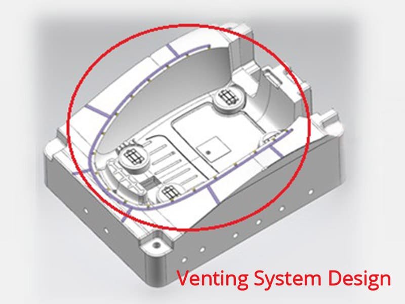
A lifter design needs good cooling, venting, and lubrication. The lifter head leaves little room for cooling channels, so high-conductivity inserts near the head help reduce sink marks. Small vents around the head also let trapped gas escape and prevent burn marks. Lubrication grooves on the sliding surfaces hold grease and keep the lifter moving smoothly.
Conclusion
A lifter does quiet but critical work inside the mold. Each choice, from the lifter type to the guide angle and the wear surface, decides how long that lifter keeps working and how well the product comes out of the mold. Erye provides injection mold service with lifters across many part families, from small clips to large panels. That hands-on experience shapes every lifter layout we propose, from the first angle check to the final trial run.