Snap fit joints, also known as snap hook, snap fastener, or retention position, is a commonly used connection and fixation structure in product design. It generally requires another mating part to achieve the connection effect. It is particularly common in plastic components, and there are various ways to connect two parts.
The article aims to provide a deep understanding of Snap-fit, covering its definition, pros and cons, types, design principles, common issues, solutions, and applications, helping designers integrate it wisely to avoid expensive mistakes.
What is a Snap-Fit?
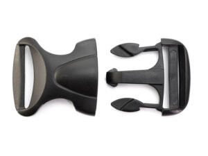
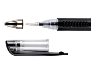
A snap fit is a simple yet effective mechanical joint that allows two parts—usually plastic—to be assembled by applying a small force until a flexible feature “snaps” into place. These features often take the form of hooks, beads, or studs that deflect during assembly and then return to their original shape to lock components together. Plastic snap fits are all around us: from pen caps and bottle lids to electronics enclosures and car interior panels.
Snap fits work without screws, adhesives, or welding. Instead, they rely on the elasticity of the material to temporarily deform and then secure the connection. Once engaged, the parts remain joined—either permanently or in a way that allows easy disassembly, depending on the design.
Their ease of use also makes them ideal for automation. And with minimal part count and no need for tools or fasteners, snap fits are one of the most cost-efficient ways to assemble parts without sacrificing strength or aesthetics.
Advantages and Disadvantages of Snap-fit Connections
Compared to other connection methods, snap-fit is a relatively economical, effective, and simple plastic connection method, specifically manifested as:
Advantages:
- Economy: Plastic snap-fits can be directly molded onto plastic parts, and during assembly, no other locking accessories, such as screws or nuts, are needed, saving costs.
- Effectiveness: The connection strength of snap-fits can meet the requirements of most product designs. In products that require higher connection strength, snap-fits can serve as an auxiliary connection, such as screws plus snap-fits.
- Simplicity and Convenience: Through reasonable design, snap-fit connections can achieve quick assembly and disassembly, and the disassembly process may not even require auxiliary tools.
At the same time, snap-fit joints are also a type of connection that can maintain the integrity of the product’s appearance well, especially in the consumer electronics field, where appearance requirements are high; snap-fit connections are the most widely used connection method.
Disadvantages:
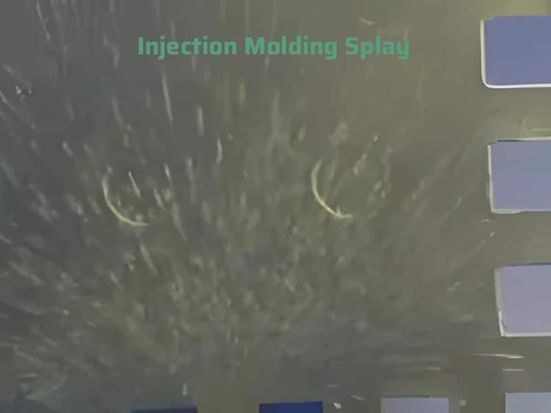
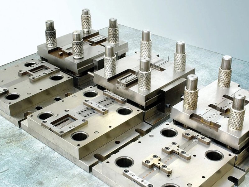
- High Mold Costs: Snap-fits often require complex mold features like inclined tops or sliding blocks, increasing mold expenses, except in specialized designs like snap-through.
- Precision Challenges: Achieving accurate snap-fit tolerances typically demands multiple mold trials, as one-shot precision is difficult.
- Hard-to-Check Quality: Some snap-fits are hidden after assembly, making it tough to verify connection quality, which can lead to improper assembly and reduced reliability.
- Limited Strength: Without sufficient engagement, snap-fits may loosen due to plastic deformation, often failing rigorous tests like drop tests.
- Finite Reusability: Most snap-fits, unless made from tough materials or uniquely designed, lose effectiveness after repeated disassembly due to deformation.
- Non-Repairable Failures: A broken snap-fit is permanently damaged, often requiring the entire part to be discarded.
Types of Snap-fit Joints
Cantilever Snap-fit Joint
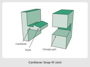
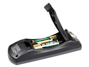
Cantilever snap fits are the most common and versatile type used in injection-molded assemblies. They consist of a flexible beam—called a cantilever—that deflects during assembly. At its end, a tapered or hook-shaped feature slides into a notch or cavity on the mating part. Once in position, the beam snaps back to its original shape, locking the parts together.
This type of joint is simple, cost-effective, and highly adaptable. It can be designed for either permanent or releasable connections, depending on the geometry and materials used. Cantilever beams can be straight, L-shaped, or U-shaped, giving designers flexibility based on available space and required performance.
Best for:
- Electronic housings
- Battery compartments
- Automotive interior panels
- Toy assemblies
Annular Snap-fit Joints
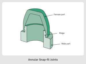
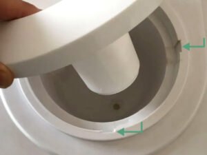
Annular snap fits are circular joints commonly used with cylindrical or round parts—think bottle caps, jar lids, or cosmetic containers. They feature a continuous ring-shaped ridge on one part that snaps into a matching groove on the mating part, providing full 360° engagement around the circumference.
During assembly, the circular ridge deflects elastically as it’s pushed over the groove, then snaps back to lock the parts together. This uniform engagement spreads stress evenly, making annular joints strong, secure, and well-suited for high-load or sealing applications—such as airtight closures or hose connectors.
These joints can be designed for temporary or permanent use. A return angle of 45° typically forms a strong but detachable connection, while 90° typically results in a permanent connection.
However, designing annular snap fits can be tricky. Predicting the engagement force requires careful consideration of geometry, material elasticity, and tolerances. Even small variations during injection molding—like shrinkage—can lead to tight or loose fits. That’s why materials with reliable shrinkage behavior, such as polypropylene or polyethylene, are commonly used.
Best for:
- Caps and lids
- Enclosure seals
- Ball-and-socket joints
- Press-fit tubing
Torsion Snap-fit joints
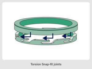
Torsion snap fits use a twisting motion to form a secure connection. Instead of bending a flexible arm like in cantilever designs, these joints rely on a rotating or spring-loaded feature—typically a beam or latch—that twists into place when two components are pressed together. Once engaged, the torsional force holds the parts firmly in position.
The twisting action works much like a seesaw. As the mating part enters, the snap feature rotates or flexes sideways, then springs back to lock into a notch or groove. This makes torsion snap fits ideal for hinged assemblies that require frequent opening and closing.
Best for:
- Hinged containers
- Snap-on lids with rotating locks
- Quick-access housings and enclosures
U-Shaped Snap Fit
U-Shaped Snap Fit Joints
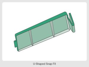
U-shaped snap fits are a variation of cantilever snap joints, distinguished by their U-shaped beam that flexes during assembly. Think of it as a cantilever arm folded back onto itself—the doubled structure allows for added flexibility in tight spaces where a full-length cantilever beam wouldn’t fit.
During assembly, the U-shaped feature compresses inward as it’s pushed into a mating slot or groove, then expands outward to lock the components together. This dual-ended flexibility provides better alignment tolerance and makes the joint more forgiving during assembly.
Common Applications:
- Clip-on covers
- Electronic housings
- Cable routing clips
- Automotive interior trim
- Modular enclosures
Comparison of Types of Snap Fit
Design Principles and Key Points
Before designing snap-fits, it is essential to understand the following key factors:
- The mechanical properties of the plastic material you plan to use.
- The expected number of assembly and disassembly cycles.
- The stresses and strains the snap-fit will experience during assembly.
- The mechanical loads acting on the snap-fit after assembly.
Snap-Fit Dimensions
Dimensions must provide sufficient strength and flexibility so the snap-fit does not fracture during assembly or disassembly. Proper sizing is therefore essential. A typical straight cantilever snap-fit is commonly sized as follows:

- Snap thickness t = 0.5–0.6 × nominal wall thickness T.
- Root fillet Rmin = 0.5 × t.
- Height H = 5–10 × t.
- Lead-in angle α = 25°–35°.
- Disassembly angle β:
- β ≈ 35° for tool-free, removable assemblies;
- β ≈ 45° for assemblies that require a small external force to remove;
- β ≈ 80°–90° for assemblies intended to be effectively non-removable (high removal force).
- Snap tip thickness Y ≤ t.
The thickness and height of the snap-fit are the primary factors determining its strength and elasticity. If the snap-fit is too thin, its strength will be weak, and it cannot withstand large assembly forces. If it is too thick, the snap-fit will lack elasticity, leading to breakage due to insufficient deflection during assembly, and the corresponding plastic wall may also exhibit shrinkage defects.
Different plastic materials have varying parameters such as elastic modulus, resulting in differences in snap-fit dimensions. These can be calculated using relevant formulas. Of course, the best approach is to verify the snap-fit dimension design through finite element analysis (FEA) to ensure it meets the load requirements.
Add a Fillet at the Snap Root to Avoid Stress Concentration
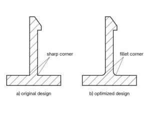
The most common failure mode is a fracture at the snap root caused by a sharp corner that concentrates stress. Avoid sharp transitions—provide a root fillet at least half the snap thickness to reduce stress concentration and improve fatigue life.
How to design fillet and chamfer? Click to read the design guideline.
Even Distribution of Snap-Fits
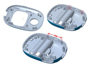
When two parts connect via snap-fits, place snaps evenly around the perimeter so the load is shared uniformly. If the part tends to deform, position snaps closer to deformation-prone areas (for example, corners) to stabilize the assembly.
Use Locating Pins for Assembly Guidance and Dimensional Accuracy
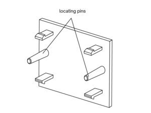
Relying solely on snap-fits can limit assembly accuracy because snaps typically have larger dimensional tolerances. Adding locating pins and holes helps:
- Ensure precise alignment and maintain assembly dimensions.
- Guide parts during assembly—if locating pins are slightly taller than the snap features, they engage first and align components before the snaps engage, improving assembly speed and consistency.
- Protect snaps from damage caused by rough assembly by controlling the mating sequence and contact points.
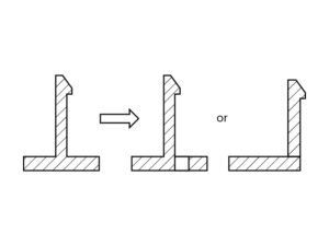
Manufacturing Feasibility and Cost
Unreasonable snap-fit designs can easily increase the complexity of injection molds, requiring lateral core-pulling mechanisms and thus raising mold costs. Proper snap-fit design optimization can simplify the mold structure. For example, adding an opening at the snap-fit root can avoid undercuts, eliminating the need for lateral core-pulling in the injection mold and simplifying the mold structure.
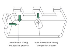
If the snap-fit is ejected using an angled lifter, check for interference during the ejection process. The head of the angled lifter cannot be slanted (with an angle between the top surface and the ejection direction less than 90°); otherwise, the angled lifter cannot retract smoothly.
Design for Easy Mold Modifications
Snap-fit dimensions often need iterative tuning (length, thickness, deflection, etc.) to meet assembly requirements. It’s pragmatic to start with slightly undersized snap features instead of finalizing maximum dimensions on the first trial—this makes later mold modifications easier and less costly.