Mold alignment gets less attention than cavity steel or cooling layout, yet it shapes part quality on every cycle. When the injection mold guide system works well, thin cores stay intact, parting lines stay tight, and shut-off faces last longer. When it wears out, those problems show up fast. This guide covers the main parts of it, how the system works, and how to select the right setup.
What Is an Injection Mold Guide System?
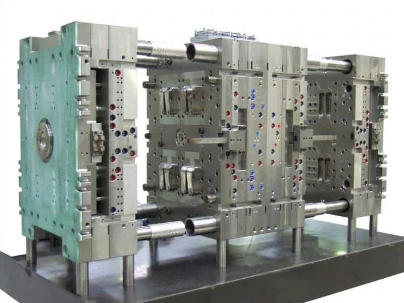
An injection mold guide system is one of the injection mold parts. It consists of precision components that guide the moving half of the mold into the fixed half. The set usually includes guide pins, guide bushings, and sometimes guide pillars. These parts control the direction of travel. They also give the first level of alignment before the cavity and core touch.
A properly specified guide system delivers three practical benefits:
- Part quality: The pins keep the core centered in the cavity on every closing. Wall thickness stays uniform, and the parting line stays tight enough to block flash.
- Mold life: The guide system takes the wear caused by the sliding contact when the mold closes, so the shut-off faces stay intact. Replacing worn bushings on schedule restores alignment and extends the mold’s service life.
- Production stability: An aligned mold closes the same way every cycle, so flash, short shots, and broken cores appear less often. Fewer defects mean fewer stops for cleaning, sorting, or repair.
Guide System vs Positioning System
Many people use the two terms as if they mean the same thing, yet each one handles a different job. The guide system brings the mold halves together. The positioning system locks them into the exact final spot and holds them there.
| Item | Guide System | Positioning System |
|---|---|---|
| Main job | Guides motion during opening and closing | Sets the final position and resists side load |
| When it acts | Throughout the stroke | At the end of closing, and during injection |
| Typical parts | Guide pins, bushings, pillars | Parting line locks, taper locks, side locks, taper pins |
| Fit | Close sliding fit with running clearance | Tight taper contact with no free play |
| Accuracy level | Coarse to medium alignment | Fine alignment |
Main Parts of Injection Mold Guide System
A typical mold guide system combines pins, bushings, and a few support features. Each part has its clear role.

Guide Pins (Leader Pins)
Guide pins are hardened, ground rods that sit in one mold half and slide into the other. Most are hardened to roughly 56 to 62 HRC and finished with a fine grind. Two types are common, and they differ in how the plate holds them.
- Straight pins have no collar. They press into a plain bore, and the fit holds them in place. Their simple shape often suits smaller molds and shorter runs.
- Shoulder pins have a collar that locks them against the plate, so they resist being pulled out. They often suit larger molds and long production runs.
Guide Bushings
Guide bushings are sleeves in the opposite plate that receive the pins. They come in two common body styles. Straight bushings press into a plain bore, and headed bushings have a collar that locks them against the plate. Many also carry oil grooves or self-lubricating inserts to cut friction. A hardened pin usually pairs with a bushing of different hardness or material. That pairing sends the wear to the bushing, which costs less to replace.
Guide Pillars
Large molds need a stronger version of the main guide set. Heavy guide pillars replace standard pins, because a big moving half weighs enough to sag on standard pins and drag across the bushings.
Mold Plates
Mold plates carry the pins and bushings, so they set the accuracy ceiling for the whole guide system. The fixed half and the moving half each hold one set of bores. The pin bores go in the moving half. The bushing bores go in the other half. The two sets must sit in matching positions, and each bore must run square to the plate surface. The plates also need enough steel around each bore to take the side load that builds up as the mold closes.
Configuration of the Guide Pin and the Guide Bush
The layout and fixing method determine how long a guide system stays aligned. Even a good pin and bush lose accuracy when they sit in the wrong place or work loose in the plate.
- Pin to bushing: This pair uses a sliding fit, commonly H7/h7 or H8/h8. The small running gap lets the pin slide freely while it stays centered.
- Pin or bushing to plate: This pair uses a transition fit, commonly H7/k6 or H7/m6. The fit holds each part firmly in its bore with no play.
- Contact length: The pin and bushing touch over about 1.5 to 2 times the pin diameter. The rest of the bore is relieved by about 0.5 to 1 mm. The relief reduces friction and limits the area that needs precision machining, making it easier to hold tolerance.
Key Design Considerations for a Mold Guide System
A well-designed mold guide system requires more than selecting the right guide pins and bushings. Their materials, quantity, arrangement, and lubrication all affect mold alignment, wear resistance, and assembly accuracy.
Guide Material
Match the pin and bushing materials to production volume and cleanliness needs. Standard hardened steel suits general production. For high-volume molds, nitrided pins and wear-resistant bushings offer better resistance to friction and wear. Food-contact and medical applications may require self-lubricating bushings to reduce the risk of grease contamination near the mold cavity.
Guide Quantity
The layout of a standard mold typically uses 2 to 4 pin and bushing pairs, spread around the parting surface. Small molds, round or rectangular, often use only two pairs. Large and medium molds often use 3 or 4 pins of the same diameter in an asymmetric layout. That layout simplifies machining and stops the plates from going together the wrong way.
Lubrication
Lubrication keeps a thin grease film between the pin and the bushing, so the two never touch metal to metal. Without that film, the surfaces scuff and wear fast. A thin coat of heat-resistant grease on the pin is enough, because excess grease squeezes out, collects dust, and can reach the cavity. Oil grooves in the bushing hold grease along the stroke. Molds that must stay grease-free use self-lubricating bushings with graphite inserts instead.
Asymmetric Guide Pin Arrangement
Guide pins can be arranged asymmetrically to prevent incorrect mold assembly. For example, one guide pin can be positioned slightly off-center, or one pin can have a different diameter from the others. This arrangement allows the mold plates to fit together in only one orientation. Without this feature, a symmetrical mold plate could be rotated 180 degrees during reassembly without being noticed.
Additional Alignment and Locking Features
Tall cores, thin walls, long molds, and off-center gates can create lateral forces during injection molding. These forces may cause the mold halves to shift if the guide pins alone cannot provide sufficient support. In such cases, taper locks or parting line interlocks provide additional alignment and resist lateral movement.
Conclusion
Guide system design has a direct effect on how accurately an injection mold operates. A configuration that works for a small mold may not provide enough support for a larger mold or one exposed to significant lateral forces. Pin arrangement, bushing fit, lubrication, and additional locking features should therefore match the mold’s structure and operating requirements.
Erye provides injection mold services from design review through tooling. You can send your 3D model, resin choice, and target volume, and our team will review the guide and positioning setup before steel is cut.