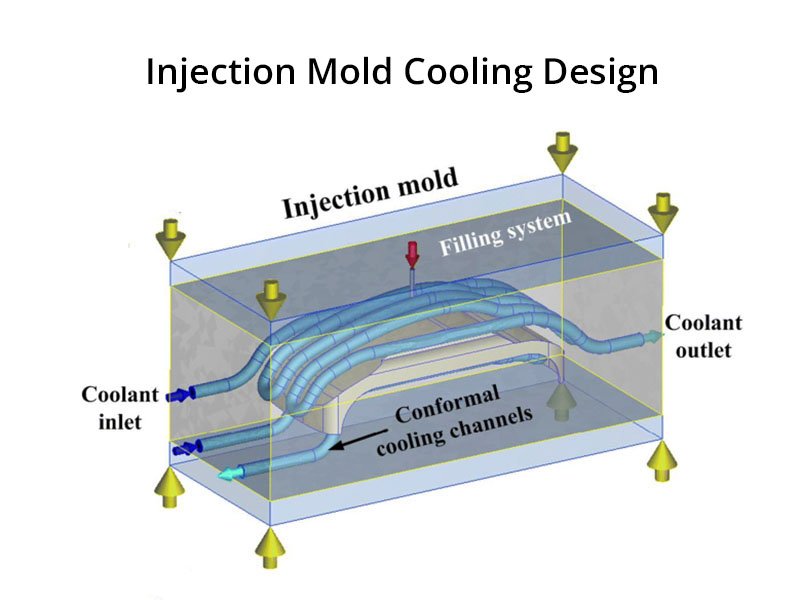
In injection molding, the cooling phase plays a critical role in determining the overall cycle time and the quality of the molded parts. Mold cooling refers to the process of removing heat from the molten plastic within the mold to solidify it into the desired shape. Effective mold cooling can account for up to 80% of the total cycle time, making it essential for optimizing production efficiency.
Selection of Cooling Mediums
The choice of cooling medium is fundamental in mold cooling systems.
Water is the most commonly used medium in injection mold cooling due to its high specific heat capacity of approximately 4.18 kJ/kg·°C and high heat transfer coefficient. These properties allow water to absorb and transfer heat efficiently from the mold surfaces. Additionally, water is inexpensive and readily available, making it suitable for most applications.
Compressed air serves as an alternative in specific scenarios, such as cooling thin or elongated cores where water channels might be impractical. Air has a lower heat capacity but can be effective for localized cooling.
Condensate water, often from chilled systems, is another option, providing consistent low temperatures but requiring additional infrastructure for condensation management.
Mold Cooling System Design Principles
When designing a mold cooling system, cooling circuits are generally designed reasonably in parts, such as the cavity and core, and the mold temperature is controlled by adjusting the flow rate and velocity of the cooling water. In order to improve the efficiency of the cooling system and make the temperature distribution on the surface of the cavity uniform, the following principles should be followed when designing the cooling system.
Proper Cooling Channel Layout
The layout of cooling channels is one of the most important aspects of cooling design. Proper channel placement allows heat to be removed evenly from the mold and prevents temperature variations across the cavity.
In molds where the plastic part has uniform wall thickness (picture a), cooling channels should be arranged so that the distance from the channel to the cavity surface remains relatively constant. This approach promotes uniform heat transfer across the mold surface.
In cases where the part wall thickness varies (picture b), the cooling design must adapt accordingly. Thicker sections generate more heat and require intensified cooling. Channels should be placed closer together and nearer to the surface in these areas to enhance heat extraction.

Optimizing Cooling Channel Diameter and Spacing
The diameter and spacing of cooling channels significantly affect the temperature uniformity in mold cooling. Larger cooling channels allow greater coolant flow and improved heat removal. At the same time, an increased number of channels can help distribute cooling more evenly across the mold surface.
In a mold with identical minimum distances from channels to the cavity, using multiple larger channels results in more uniform surface temperatures. For example, in the follow picturer, picture (a) shows that five channels with a bigger diameter might yield temperature variations of only 0.05°C (from 60°C to 60.05°C), whereas picture (b) shows that two smaller channels could lead to fluctuations up to 8.33°C (from 53.33°C to 61.66°C). Therefore, in cooling design, it is advisable to incorporate as many channels as the mold structure permits, prioritizing larger cross-sections to minimize temperature gradients.

Proper Distance from Cooling Channels to the Cavity Surface
The distance between the cooling channels and the cavity surface directly affects whether the cavity cools uniformly and influences the mold’s rigidity and strength. It is incorrect to assume that placing the channels closer to the surface always improves cooling performance.
In practice, the placement of cooling channels is often constrained by components such as ejector pins, inserts, and side-core mechanisms. It is not always possible to position channels at ideal locations, and the spacing between channels may end up larger than desired. When channels are positioned too close to the cavity surface under these conditions, cooling uniformity suffers because heat extraction becomes overly localized in certain areas while remaining inadequate in others.
At the same time, the determination of this distance must take into account the strength and rigidity of the mold material. Placing channels too close risks causing material deformation or distortion under the high cavity pressure during injection, which leads to surface cracking or crazing on the cavity surface, compromising mold life and part quality. As the following figure shows, the recommended distances between cooling holes and the cavity surface should be 1.5D~2D. The distances between cooling holes should be 3~5D. That will get a balance among cooling efficiency, temperature uniformity across the cavity, and the mold’s structural integrity (rigidity and strength).

Controlling Inlet and Outlet Temperature Differences
Maintaining a small temperature difference between the inlet and outlet water is essential for uniform mold cooling. For general plastic parts, this difference should be kept below 10°C. And for precision parts, the temperature difference should be under 2°C.
The temperature difference between the inlet and outlet water can usually be reduced by changing the arrangement of the cooling water channels. As shown in the following figure.
In the structure shown in Figure (a), the temperature difference is large due to the long pipes. That will lead to uneven cooling of the plastic part.
In the structure shown in Figure (b), the temperature difference is smaller due to the shorter pipe length. That will lead to a better cooling effect.
To achieve this, cooling designs should favor shorter channel paths or parallel configurations over long, serial ones. For instance, a single long channel might result in a significant temperature rise from inlet to outlet, causing non-uniformity. Dividing the system into multiple shorter loops reduces this issue, improving overall injection mold cooling effectiveness.

Enhanced Cooling at Gate Areas
Gate areas experience the highest temperatures during filling due to the entry of molten plastic. Therefore, mold cooling must prioritize these zones. Positioning the inlet near the gate allows cooler water to absorb heat immediately, reducing peak temperatures.
In side-gate designs (Figure a), channels should encircle the gate closely. For multi-point gate (figure b)s, separate circuits or zoned cooling can be implemented. This targeted strategy in cooling design prevents issues like gate vestige marks and ensures consistent part quality.

Additional Considerations in Cooling Design
Beyond the primary principles, several factors enhance mold cooling reliability.
- Channels should avoid areas prone to weld lines, as excessive cooling there can exacerbate visible defects.
- Cooling channels sealing is important; channels should not pass through inserts unless sealed with sleeves to prevent leaks.
- Ease of machining and cleaning is another aspect. Channels must be straight or gently curved for drilling and maintenance.
- Inlet and outlet fittings should be located on the same side of the mold, preferably the rear, for operational convenience.
- Ensuring smooth flow without dead zones prevents water stagnation and corrosion.
Conclusion
Effective mold cooling will maintain product quality and efficient injection molding production. By applying these principles during mold design, we can achieve shorter cycle times, improved dimensional accuracy, and more consistent molding performance.