
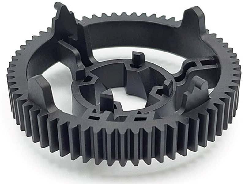
How do you deliver lighter components and stronger structures while maintaining strict dimensional tolerances? Relying on custom composite molded parts is the standard methodology for metal-replacement projects in automotive, industrial, and consumer electronics. However, transitioning from an unreinforced polymer to a composite material, whether it is a high-volume glass-filled nylon (PA66-GF) or an ultra-performance carbon-filled PEEK, fundamentally changes how a material behaves inside the tool. The changes in material behavior introduce processing challenges. Flow behavior, fiber orientation, shrinkage, and tooling wear must all be carefully managed to achieve consistent quality.
What is Composite Material?
Composite materials consist of a polymer base matrix reinforced with fibers, particles, or other functional additives. Unlike neat resins, composites are non-homogeneous materials engineered to achieve mechanical and thermal properties that neither constituent can provide alone. Common reinforcements include glass fiber, carbon fiber, and mineral fillers, which are compounded with base resins ranging from commodity polymers like PP and PA to high-performance thermoplastics like PEEK and PPS.
Why Are Manufacturers Switching to Composites?
The composites’ advantages are obvious.
First, weight reduction. Composite parts can slash mass by 30% to 60% compared to metal equivalents while maintaining structural integrity. That matters enormously in electric vehicles, aerospace, and portable electronics.
Second, enhanced mechanical performance. Higher tensile strength, improved flexural modulus, and better fatigue resistance become standard. Parts withstand repeated stress, vibration, and harsh environments far better than unreinforced plastics.
Third, design flexibility. You can integrate ribs, bosses, snap fits, insert molding, and overmolding in one shot. Complex geometries that once required multiple assembly steps now emerge complete from the mold.
Common Composite Materials We Mold
Selecting the correct matrix and reinforcement combination depends on the thermal, mechanical, and cost requirements of the application. The following table provides a direct comparison of the primary composite materials processed at Erye:
| Material System | Key Advantages | Typical Applications |
|---|---|---|
| PP + Glass Fiber (PP-GF) | Low cost, low density, excellent moisture resistance. | Automotive interior modules, structural shrouds. |
| PA66 + Glass Fiber (PA66-GF) | High tensile strength, high heat deflection temperature (HDT), good oil resistance. | Automotive under-hood components, power tool housings. |
| PPA + Carbon Fiber (PPA-CF) | High stiffness, low moisture absorption, excellent dimensional stability. | Structural brackets, consumer electronics chassis. |
| PEEK / PPS + Carbon Fiber | Ultra-high thermal resistance, chemical inertness, extreme mechanical strength. | Aerospace components, medical devices, semiconductor tooling. |
Key Challenges in Composite Injection Molding and Solutions
Composite materials offer powerful properties. However, those same properties create distinct hurdles during injection molding.
1. Flow Resistance and Cavity Filling
Composite materials have higher viscosity than neat polymers, which can result in incomplete cavity filling, short shots, internal voids, and uneven fiber distribution, especially in thin-walled or complex parts. Fiber or particle reinforcement may further impede flow.
Erye’s Solution:
We expand gate cross-sections and utilize a progressive, multi-stage injection velocity profile to maintain a stable shear rate, ensuring the melt reaches thin-walled extremities without shearing the fibers into uselessly short fragments. For composite parts, ensure the gate depth is at least 0.8 times the wall thickness at the injection point to prevent premature gate freeze-off.
2. Fiber Orientation and Mechanical Performance
Reinforcing fibers align along the flow path, creating anisotropic mechanical properties. Uncontrolled fiber orientation can cause weak points or inconsistent stiffness and strength across the part.
Erye’s Solution:
We strategically position gates and adjust flow paths to direct fiber orientation along primary load directions. Through precise control of injection speed and packing pressure, we manage fiber alignment during filling and solidification. Mold geometry is carefully designed to minimize turbulence, and predictive simulations guide our decisions to ensure that the final part consistently achieves the desired mechanical properties.
3. Shrinkage and Warpage
Composite parts exhibit non-uniform shrinkage due to anisotropic reinforcement and differential cooling rates. Uneven shrinkage can result in warpage, dimensional deviation, and misfit in assembly-critical parts.
Erye’s Solution:
Erye addresses shrinkage by designing uniform wall thicknesses wherever possible and incorporating mold compensation based on empirical data. Cooling channels are balanced to maintain even temperatures, and part geometry is refined to control fiber-induced shrinkage.
4. Mold Wear and Tooling Durability
Reinforcing fibers are abrasive and can accelerate wear on mold surfaces. High-wear molds reduce part consistency and increase surface defects over time, and they increase maintenance costs.
Erye’s Solution:
We use hardened steels (H13 or SKD61 tool steel) and wear-resistant coatings in high-shear areas and carefully design gates and runners to minimize direct fiber impact on critical mold surfaces. Regular preventive maintenance and inspections ensure long-term consistency, and high-wear inserts are replaced selectively to avoid full mold downtime, extending mold life and maintaining part quality.
5. Surface Quality and Cosmetic Requirements
Fibers or fillers can create surface roughness or “read-through,” especially on cosmetic or functional surfaces. Inconsistent fiber distribution exacerbates this issue.
Erye’s Solution:
We address surface quality by optimizing packing pressure and mold temperature to improve surface replication. Resin-rich layers can be applied to cosmetic-critical areas, and fiber type and length are selected to minimize surface imperfections. In cases where a strict surface finish is required, post-processing is integrated into production to ensure that both appearance and functional tolerances are consistently met.
Applications of Composite Injection Molded Components
Composite injection molded parts are widely used in industries requiring strength, durability, and lightweight construction:
- Automotive and EV: Battery enclosures, structural brackets, interior trim, and under-hood components.
- Aerospace and Defense: Lightweight panels, drone frames, and non-critical structural parts.
- Consumer Electronics: Rigid, thin-wall housings.
- Industrial Equipment: Pump housings, robotic grippers, and durable components.
- Sports and Outdoor Gear: Performance parts that balance strength with low weight.
Conclusion
Composite injection molding offers significant advantages in strength, stiffness, and durability. At the same time, it introduces complex challenges. Partnering with an experienced custom injection molding supplier reduces development risk, improves consistency, and ensures that components meet both functional and dimensional requirements. As a dedicated custom injection molding supplier, Erye delivers complete support from concept to full-scale production. Contact Erye and get high-quality solutions tailored to your project.
You May Also Like These Articles
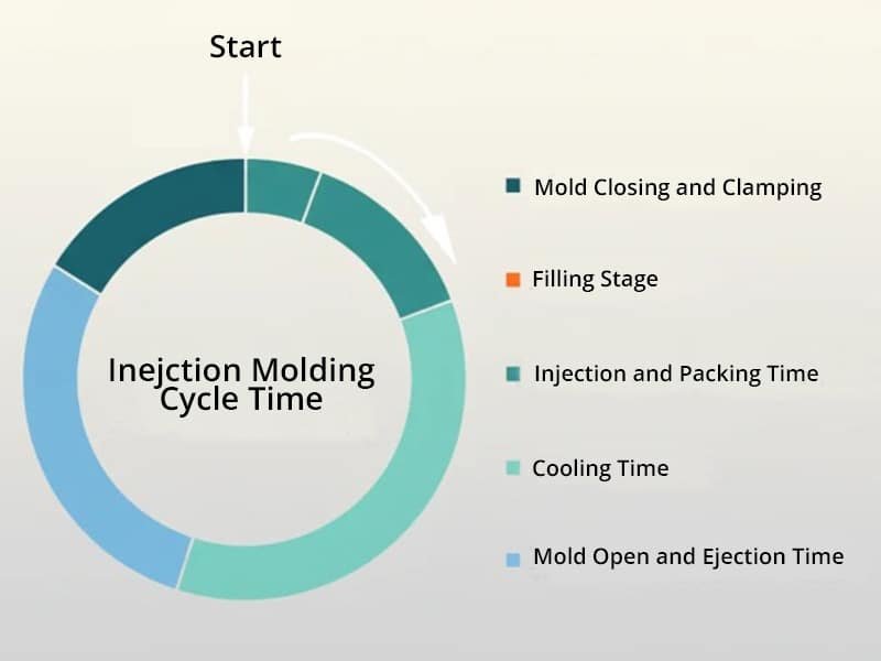
What is Injection Molding Cycle Time Injection molding cycle time refers to the total duration
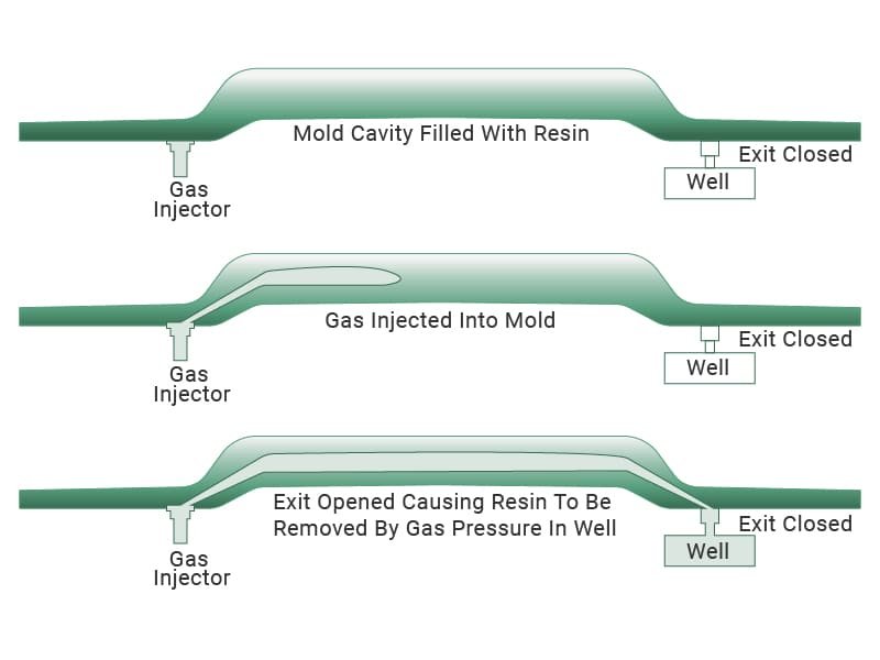
Gas-assisted injection molding offers a method to produce plastic components with internal hollow sections. The
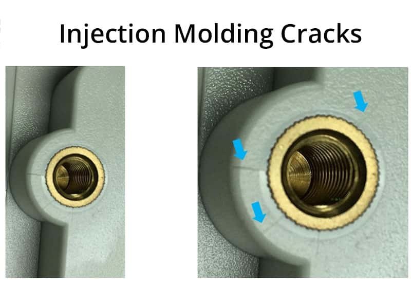
Injection molding cracks are a frequent issue in plastic part production. This defect affects part
Flash is an unavoidable defect of molding processes, occurring as excess material along parting lines,
Fillet machining turns a sharp internal corner into a smooth and rounded transition, and that

Plastic finishes refer to the surface treatments applied to molded plastic parts, primarily during the
Contact Us
If you are interested in our products, you can leave us a message via the form below and we will get back to you within 8 hours!