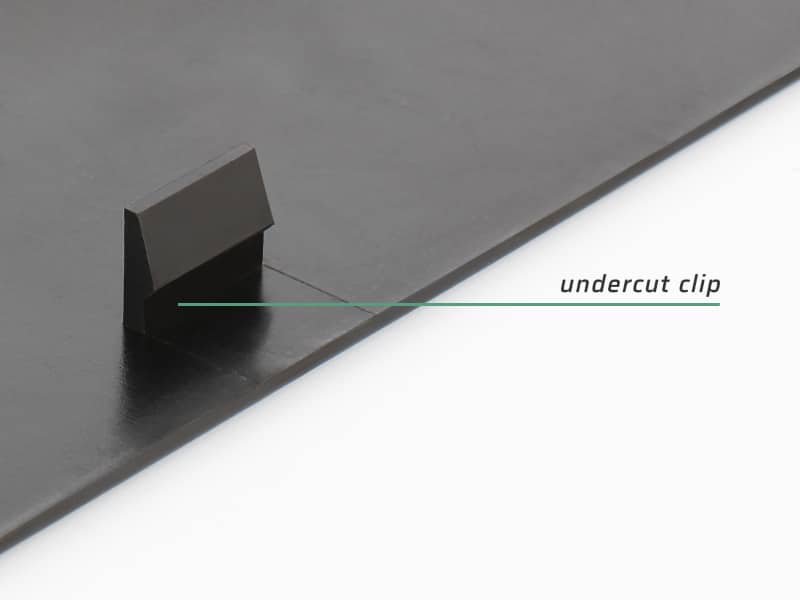
Injection molding undercuts is any protrusion or recessed feature on a plastic part that prevents it from being ejected straight out of a two-piece mold. In other words, the cavity and core become “die-locked” by this feature, so the part cannot be removed without special mold actions. Undercuts can be external (on the part’s outer surface) or internal (in hidden cavities).
These molding undercuts enable very complex geometries – for example, helical screw threads, snap-fit latches or cable ports – to be formed directly in the part. In short, Injection Molding Undercuts allow parts to include features like snaps, hooks or through-holes without assembly, but they add complexity to the mold design.
Injection molding undercuts arise whenever a part must have features beyond the simple mold draw. For example, the built-in threads on a plastic screw or the tab on a snap-fit enclosure are undercuts that enhance functionality. Although they increase the tooling cost, they often eliminate post-molding assembly or machining. Undercuts are only included when necessary, because they make the mold more complex and expensive. In this blog, we’ll explain why undercuts are used, how to design them successfully, and what best practices and applications to consider.
Why Are Undercuts Used in Injection Molding?
In plastic injection mold design, undercuts allow you to integrate complex features—molded threads, snap‑fit latches, interlocking geometries, and through‑holes—directly into a single part, eliminating the need for secondary machining or assembly. There are some necessary case scenarios of undercuts in injection molding:
- Threads for plastic fasteners: Internal or external screw threads allow parts to be screwed together without metal hardware. For example, a bottle cap’s helical thread is a molded undercut.
- Interlocking snaps and latches: Features like spring clips or snap-fit tabs (seen in clamshell housings and cases) are undercuts that lock parts together. These replace separate clips or screws.
- Barb fittings and conduits: Hose barb connectors and fluid passages (common in medical and plumbing parts) rely on undercuts to grip tubing and seal without additional assembly.
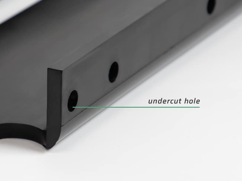
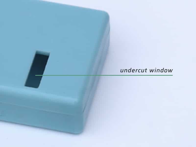
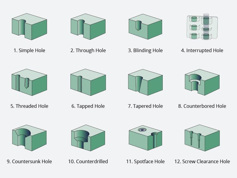
- Side holes and slots: Molded openings for wires, buttons, or ports (such as cutouts in an electronics enclosure) often use undercuts so that the hole stays intact when ejecting the part.
- Coring thick sections: Molders use internal undercuts to “core out” thick areas of a part, creating thin ribs or holes that reduce material and avoid sink marks. By relieving thick sections, undercuts reduce weight and warping during cooling.
In these scenarios, the benefit of the undercut is to enhance the part’s function or aesthetics without requiring secondary work. For example, an undercut snap-fit latch lets two halves click together on the fly, rather than having to glue or screw them. Similarly, a molded hole for a cable or a threaded boss means less manual assembly downstream. However, every undercut complicates the mold and adds tooling cost. Good product design involves deciding when an undercut is truly required for the part’s performance, versus when it can be avoided by a smart redesign.
Create Successful Undercuts in Molded Parts
Undercuts in injection molding are intricate features that complicate the manufacturing process by preventing parts from being ejected from the mold in a simple, straight pull. These elements demand a high level of technical expertise, often requiring specialized mold designs—such as side actions or clever modifications—and a deep understanding of the process. Despite their complexity, undercuts can be effectively managed through strategic design improvements and optimized manufacturing techniques. The best approach depends on multiple factors, including part geometry, material selection, production volume, cost constraints, and required dimensional accuracy. Here are some practical solutions:
Placement of Part Lines
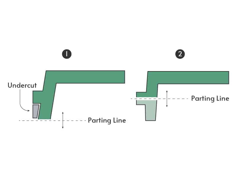
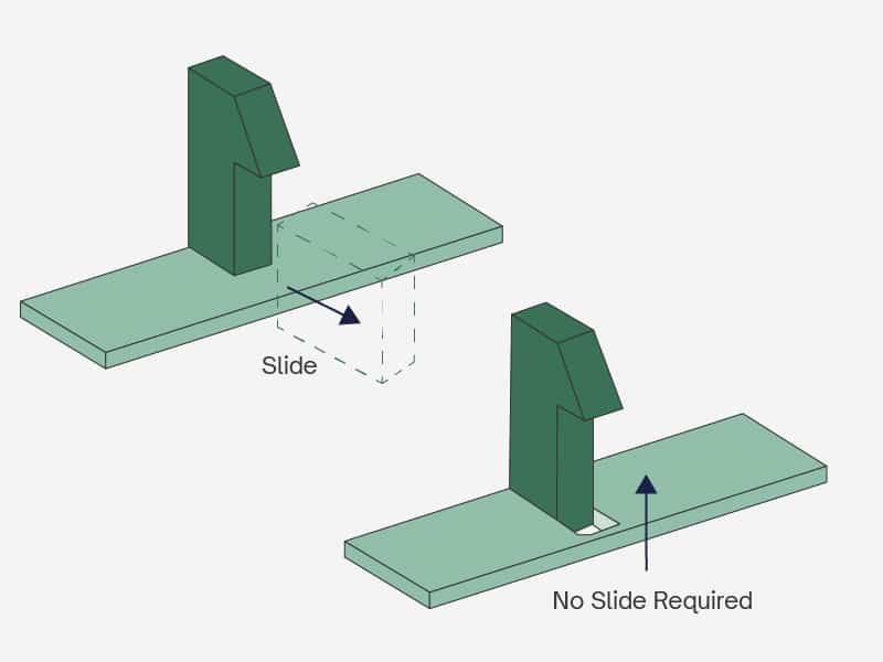
Repositioning the parting line to bisect an undercut often eliminates the need for additional mold actions. When the split plane overlaps the protruding feature, each mold half frees the part without trapping. A straight or zigzag parting line can intersect multiple standoffs or ribs in a single move. Regardless of shape, sufficient draft on adjacent walls remains essential to prevent scraping during ejection. Part geometry, material flow characteristics, and mold orientation can constrain parting‑line placement, so provision for side‑actions or collapsible cores is recommended as a backup.
Side Actions
Side actions rely on sliding core inserts that move perpendicular to the main opening direction, making it possible to release undercuts on cylindrical or tubular parts—think hose barbs or control knobs—without damaging the molded geometry. As the mold opens, an angled cam‑pin mechanism synchronizes the side‑action insert’s retraction, freeing the undercuted profile at exactly the right moment. Because the slide must operate at a precise perpendicular angle, the mold tooling requires additional guide pins and cam paths, which increases complexity and cost.
Materials choice also plays a role: rigid, low‑adhesion resins such as nylon, acetal and polycarbonate release cleanly from the side‑action slide, whereas soft or highly elastic formulations often perform better with alternative methods like bump‑off cores.
Bump Offs
Bump‑offs offer a straightforward undercut solution for flexible parts such as lens covers or snap‑in container caps. A precisely machined insert—bolted into a matching mold pocket—creates the undercut, and during ejection the plastic material compresses over its smooth, well‑radiused leading edge, allowing release without damage. This technique works best with highly deformable resins like LDPE, TPE, TPU or even liquid silicone rubber (LSR), which tolerate repeated flexing.
To prevent ejector pins from marring the part, an ejector plate is often added, providing a larger surface for uniform ejection. Some key design constraints include ,
- Ennsuring the part’s flexibility to prevent deformation or damage.
- Locating the bump‑off away from stiffening ribs or sharp corners.
- Maintaining a lead‑in angle of roughly 30°–45° so the material can slip past the bump without tearing.
Hand-Loaded Inserts
Before each injection, manually placed the machined metal inserts into the cavity to block resin flow in the targeted regions—such as sharp‑angled lips or holes in awkward positions. Once the molding cycle finishes, the part and inserts are ejected together, and the inserts are removed, cooled, and reused. This manual intervention adds to cycle time and requires operators to handle hot components safely—typically with gloves and other PPE—and favors lower‑volume or prototype runs where tooling simplicity outweighs automation. Insert dimensions should balance ease of handling (often around ½ inch square or larger) against cavity layout, and the total number of inserts is dictated by the undercut geometry and part size.
Telescoping Shutoffs
A telescoping shutoff integrates a precision‑machined “telescope” into one mold half that extends into the opposite side during injection, temporarily blocking resin flow to form hooks, clips or snap‑fit features. This approach can replace side‑actions, inserts and bump‑offs, streamlining tool complexity and reducing cost. Accurate shutoff function depends on tight tolerances and generous draft angles—typically at least 3° on vertical surfaces—to prevent metal‑to‑metal rubbing, flash formation or premature tool wear. When designed correctly, sliding shutoffs deliver reliable undercuts without adding separate mechanisms, provided all mating surfaces maintain the required taper and clearances for smooth operation.
Part Design and Secondary Operations
Part geometry should be optimized before tooling. At Erye Molding, we start with a comprehensive DFM review that identifies undercut zones, verifies draft angles against material specifications, and confirms uniform wall thickness. Strategic ribs reinforce large flat areas, internal corners receive generous radii, and thick sections are cored out to prevent sink marks—while surface finishes are applied only where function demands, balancing cycle time with part performance.
When undercuts cannot be eliminated through geometry changes, secondary operations provide a practical alternative. Instead of adding complex slides or collapsible cores, a drilled or milled hole created on a drill press or CNC center can achieve the same feature. For low‑volume runs or prototypes, this approach often proves more economical than complex mold mechanisms.
Undercut Best Practices
It is important to follow the mantra: simplify – eliminate undercuts when possible. When you cannot, at least control their impact by good design. Balancing design requirements with manufacturing realities will lead to the most cost-effective solution for any undercut injection molding challenge.
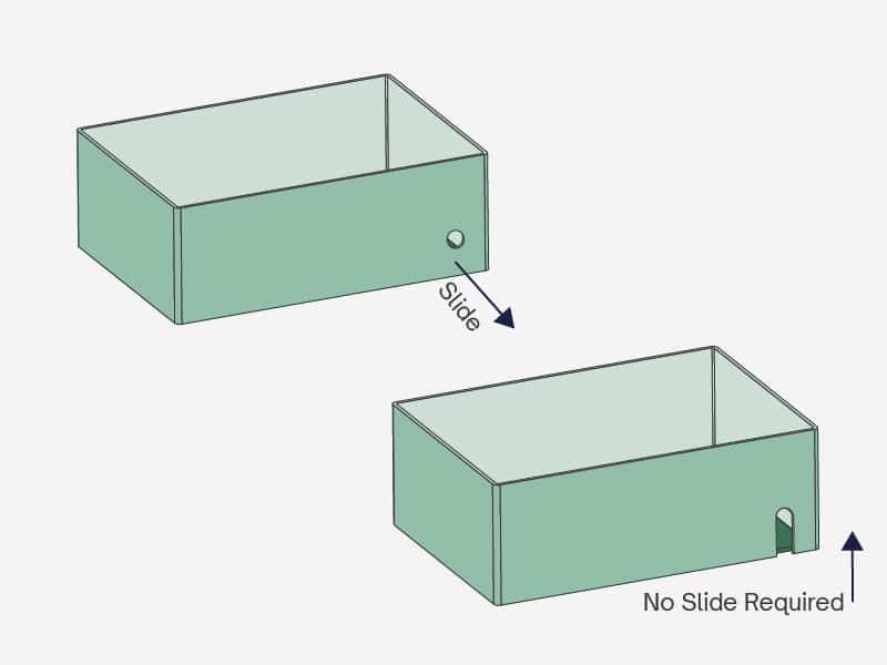
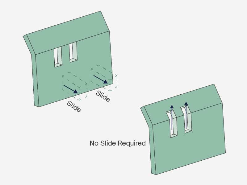
Here are three common undercuts often found in molded parts, along with three design strategies to eliminate or minimize them. Keep in mind that, depending on a part’s function or geometry, some undercuts may be unavoidable.